Continue to Site

Welcome to EDAboard.com

Welcome to our site! EDAboard.com is an international Electronics Discussion Forum focused on EDA software, circuits, schematics, books, theory, papers, asic, pld, 8051, DSP, Network, RF, Analog Design, PCB, Service Manuals... and a whole lot more! To participate you need to register. Registration is free. Click here to register now.

[SOLVED] GSM modem interfacing to AT89C51

Status
Not open for further replies.

amit251291

Member level 1
Member level 1
Joined
Jul 18, 2012
Messages
38
Helped
0
Reputation
0
Reaction score
0
Trophy points
1,286
Activity points
1,558
hello,
Can any one please share a link for a assembly program/assembly program to interface GSM modem to AT89C51?
 

i have code in C if want i share it

- - - Updated - - -

go through following links u will get idea

**broken link removed**

**broken link removed**
 
i have code in C if want i share it

- - - Updated - - -

go through following links u will get idea

**broken link removed**

**broken link removed**

well, thank you for this links but i really need Assembly program :|
please help me :|
 

ok


what u want to do either sending or receiving from the GSM
 

hi amit251291 .... gsm modems use AT commands...you might know already...
to test the modem using HYPERTERMINAL program in windows xp... you just have to type following commands to send a particular message:

AT then press enter
OK modem's reply, if everything is ok
AT+CMGF=1 then press enter to enter text mode
OK modem's reply, if everything is ok
AT+CMGS="+91XXXXXXXXXX" i.e you have to put mobile no. you want to use inside " " and then press enter
>>YOUR TEXT and then press ctrl+z

now to send the same message using a microcontroller:
-first you will have to set serial communication mode, set its baud rate and so on.

-then to send the same text(in ASCII values),just copy each byte into SBUF wait till it has been transferred(i.e wait till TI is low) now after one line text has been sent, say the first line AT, wait for at least 20-30ms(enough delay) for which modem's reply say OK would have come.

-now send next line's text and so on.

-it should be noted although, that you will have to send an ASCII value corresponding to 'enter' and 'ctrl+z' too in the same text wherever required. look for them and rest all is almost done. one more thing, mobile number should be written along with " " and not just the number itself as a most common mistake at starting.

- the '>>' symbol written on last line before 'YOUR TEXT' is what modem replies with after entering mobile number and so you do not have to send an ASCII corresponding to it, as it is the input from modem. you just have to send your text after sending ASCII for mobile number. tell me if you have any problem. good luck
 
Thank you so much tsea for this info.
i have prepared my code.
i am posting my code here. its not showing any syntax error but i am not sure whether its logically correct or not.:???:
So please go through this code once and suggest me corrections if any :)

Code:
ORG 0000H
		MOV TMOD,#20H	   		//TIMER 1, MODE 2
		MOV TH1,#-3				//9600 BAUD RATE
		MOV SCON,#50H			//8 BIT, 1 STOP, EN ENABLED
		SETB TR1
				
		MOV DPTR,#MSG1
		ACALL H1
		ACALL DELAY
		MOV DPTR,#MSG2
		ACALL H1
		ACALL DELAY
		MOV DPTR,#MSG3
		ACALL H1
		ACALL DELAY
		MOV DPTR,#MSG4
		ACALL H1
		ACALL DELAY
		MOV DPTR,#MSG5
		ACALL H1
		ACALL DELAY
H1:  	CLR A
		MOVC A,@A+DPTR
		JZ B1
		ACALL SEND
		INC DPTR
		SJMP H1
B1:
		RET
SEND: 	MOV SBUF,A
H2: 	JNB TI,H2
		CLR TI
		RET
DELAY:  MOV R3,#50H
HERE2:  MOV R4,#50H
HERE:	DJNZ R4,HERE
		DJNZ R3,HERE2
		RET
	

ORG 300H
MSG1: DB "AT",0DH
	  DB 0H
MSG2: DB "AT+CMGF=1",0DH
	  DB 0H
MSG3: DB "ATE=0",0DH
      DB 0H
MSG4: DB "AT+CMGS=",'"8149111111"',0DH
	  DB 0H
MSG5: DB "TEXT",0X1A
	  DB 0H

	  END
 

hey amit your code is almost correct...it just needs a single correction. if we divide the whole code into two major portions , the main code which is above H1 label, and subroutines after H1 then you can also observe that after the execution of last command from main code, it enters the subroutines(even if it is not desired), as they are next to the main code. so as far as you want just to send a single message, the execution should end by last line of main code, just after executing the last 'ACALL DELAY'. otherwise it will enter the subroutines. so just make it to stay there infinitely. just put 'STAY: SJMP STAY' between the last 'ACALL DELAY' and 'H1' label.
and in case you want to send the message for a particular number of times, just load a counter and decrease it every time jumping back to first command of your 'message-sending code' i.e to 'MOV DPTR,#MSG1' such that process would end with the end of counter's value.

-you can also use your own mobile phone's gsm modem to check this code with proteus, in case you don't know already, through a model called 'COMPIM' in proteus' libraries.as follows:

-connect your phone through usb cable to your computer. you will need to have the port name to which you have connected the modem and you can find that by right clicking computer in your windows, then going to manage, then under modems, right click your phone's modem and then in properties it would have its particular port name, like com4 or com2 etc. set its maximum baud rate to 9600.

-connect your microcontroller's RXD to compim's RXD(pay attention, not TXD) and TXD to TXD. edit compim's properties, set physical and virtual baud rates to 9600, select physical port to what your mobile is connected . then just execute your code and you will get a message on number that you have used in code by your phone's gsm modem. you can even put your own number there to check on your own.

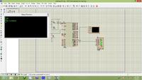
-to check the commands, that microcontroller is sending to modem, take the VIRTUAL TERMINAL device from virtual instruments mode in proteus and connect microcontroller's TXD to virtual terminal's RXD.no other connection is required. now soon microcontroller sends the commands to your modem, they will also be shown to you through virtual terminal's screen. good luck.
 
Hello tsea, Thank you for your co-operation.
here is the edited code:

Code:
ORG 0000H
		MOV TMOD,#20H	   		//TIMER 1, MODE 2
		MOV TH1,#-3				//9600 BAUD RATE
		MOV SCON,#50H			//8 BIT, 1 STOP, EN ENABLED
		SETB TR1
				
		MOV DPTR,#MSG1
		ACALL H1
		ACALL DELAY
		MOV DPTR,#MSG2
		ACALL H1
		ACALL DELAY
		MOV DPTR,#MSG3
		ACALL H1
		ACALL DELAY
		MOV DPTR,#MSG4
		ACALL H1
		ACALL DELAY
		MOV DPTR,#MSG5
		ACALL H1
		ACALL DELAY
STAY: SJAMP STAY
H1:  	CLR A
		MOVC A,@A+DPTR
		JZ B1
		ACALL SEND
		INC DPTR
		SJMP H1
B1:
		RET
SEND: 	MOV SBUF,A
H2: 	JNB TI,H2
		CLR TI
		RET
DELAY:  MOV R3,#50H
HERE2:  MOV R4,#50H
HERE:	DJNZ R4,HERE
		DJNZ R3,HERE2
		RET
	

ORG 300H
MSG1: DB "AT",0DH
	  DB 0H
MSG2: DB "AT+CMGF=1",0DH
	  DB 0H
MSG3: DB "ATE=0",0DH
      DB 0H
MSG4: DB "AT+CMGS=",'"8149111111"',0DH
	  DB 0H
MSG5: DB "TEXT",0X1A
	  DB 0H

	  END

now is it correct??

i have some doubts:
1) When we connect a modem to pc via hyperterminal and type commands modem responds with OK like responses.
Now when we are connecting it to controller, should we take into account these responses?
Or the communication will take place even if we don't consider them? In actual practice (in project) i really don't bother about these responses. In many C codes i had seen that they have sent just commands to modem and didn't bother about responses.

2) What you say about delay? Is it okay?

by the way, i don't have proteus, i will download it and will get back to you :)
 

The last program which i have posted here, is not working.


GSM modem has following on-board connections:

MAX232----->> RS232 (Female connector)

pin 7 ---> Pin 2
pin 8 ---> Pin 3

So i have done following connections after this:

RS232 (Female connector) --->> RE232(PCB male connector ) ( This o did because it was difficult to take connections from on-board Female connetor)

I took out following pins from RS232 male connector and connected to microcontroller:

RS232(PCB male connector ) ---> AT89C51
Pin 2 --> Pin 11
Pin 3--> Pin 10
Pin 5 Grounded.

Rest AT89C51 connetions:

Crystal oscillator 12 Mhz.
EN (Pin 31) -VCC
Pin 40-- VCC
Pin 20-- Gnd


Are these connetions are correct??
why my program is not working ??
 

Hello tsea, Thank you for your co-operation.
here is the edited code:

Code:
ORG 0000H
		MOV TMOD,#20H	   		//TIMER 1, MODE 2
		MOV TH1,#-3				//9600 BAUD RATE
		MOV SCON,#50H			//8 BIT, 1 STOP, EN ENABLED
		SETB TR1
				
		MOV DPTR,#MSG1
		ACALL H1
		ACALL DELAY
		MOV DPTR,#MSG2
		ACALL H1
		ACALL DELAY
		MOV DPTR,#MSG3
		ACALL H1
		ACALL DELAY
		MOV DPTR,#MSG4
		ACALL H1
		ACALL DELAY
		MOV DPTR,#MSG5
		ACALL H1
		ACALL DELAY
STAY: SJAMP STAY
H1:  	CLR A
		MOVC A,@A+DPTR
		JZ B1
		ACALL SEND
		INC DPTR
		SJMP H1
B1:
		RET
SEND: 	MOV SBUF,A
H2: 	JNB TI,H2
		CLR TI
		RET
DELAY:  MOV R3,#50H
HERE2:  MOV R4,#50H
HERE:	DJNZ R4,HERE
		DJNZ R3,HERE2
		RET
	

ORG 300H
MSG1: DB "AT",0DH
	  DB 0H
MSG2: DB "AT+CMGF=1",0DH
	  DB 0H
MSG3: DB "ATE=0",0DH
      DB 0H
MSG4: DB "AT+CMGS=",'"8149111111"',0DH
	  DB 0H
MSG5: DB "TEXT",0X1A
	  DB 0H

	  END

now is it correct??

i have some doubts:
1) When we connect a modem to pc via hyperterminal and type commands modem responds with OK like responses.
Now when we are connecting it to controller, should we take into account these responses?
Or the communication will take place even if we don't consider them? In actual practice (in project) i really don't bother about these responses. In many C codes i had seen that they have sent just commands to modem and didn't bother about responses.

2) What you say about delay? Is it okay?

by the way, i don't have proteus, i will download it and will get back to you :)


hey hi amit..sorry for replying late...first of all...the command which I told you to put...you have made a spelling mistake, it should be SJMP there and not SJAMP first try this correction. delays in your program are ok. and you do not have to worry about modem's responses as far as you only have to send a message to a particular number. one other thing that I forgot to mention in my earlier response was that you don't even need to put that 'ATE=0' command to send a message. it works well even without that command. the commands that I mentioned in my first reply, are the only necessity. although your code(with each keyword same as you posted here) was working, I just put an indefinite pause at last. so your code is correct I even tested that through my phone's modem, sent message to my own number and it worked correctly. so just correct that spelling and it should work.one other thing, before directly connecting your microcontroller to your modem, and then trying to troubleshoot error is not a better approach. you should first make sure that your code is working. use compiler like keil, for syntax error correction(which your code doesn't have fortunately) and hex file generation. then that hex file should be loaded into your microcontroller. and before doing that actually, you should even test your whole microcontroller's circuitry. you can use simulators like proteus for that.
and well, after having done that, I am sure, you won't even need any further help(you are very close). as you can troubleshoot the errors(if any arise later) yourself, and that's what the good approach for learning. however, if you need any help you can contact me here again. good luck.
 
oh yeah.. i just wonder how i put SJAMP instead of SJMP.

yep ATE=0 is also not needed.. I agree :):)

so your code is correct I even tested that through my phone's modem, sent message to my own number and it worked correctly.
:) How did you test that? the way u said it before? your words "it worked correctly" are giving me hopes :cool:;-)
I am grateful to you for your co-operation :) :) :) :)
I will follow the same approach...

I will get back to you soon :) Thank you :)
 

hi tsea,

can you please tell me again how did you test that code? i am not getting it... :?:
also here i am attaching my circuit diagram.. do you think is there need to connect extra MZX232 though one MAX232 is also there on modem? :?:

GSMCIRCUIT1.jpg
 

did u check whether the GSM is working properly or not.......

check it manually using hyper terminal and then go for microcontroller........
 

did u check whether the GSM is working properly or not.......

check it manually using hyper terminal and then go for microcontroller........


yup.. It is working well.. i have checked it on hyperterminal... :)
 

post your full code.............

why u want to go for assembly language its very hard to implement some algorithm
 

post your full code.............

why u want to go for assembly language its very hard to implement some algorithm

Code:
ORG 0000H
		MOV TMOD,#20H	   		//TIMER 1, MODE 2
		MOV TH1,#-3				//9600 BAUD RATE
		MOV SCON,#50H			//8 BIT, 1 STOP, EN ENABLED
		SETB TR1
				
		MOV DPTR,#MSG1
		ACALL H1
		ACALL DELAY
		MOV DPTR,#MSG2
		ACALL H1
		ACALL DELAY
		MOV DPTR,#MSG3
		ACALL H1
		ACALL DELAY
		MOV DPTR,#MSG4
		ACALL H1
		ACALL DELAY
		MOV DPTR,#MSG5
		ACALL H1
		ACALL DELAY
STAY: SJMP STAY
H1:  	CLR A
		MOVC A,@A+DPTR
		JZ B1
		ACALL SEND
		INC DPTR
		SJMP H1
B1:
		RET
SEND: 	MOV SBUF,A
H2: 	JNB TI,H2
		CLR TI
		RET
DELAY:  MOV R3,#50H
HERE2:  MOV R4,#50H
HERE:	DJNZ R4,HERE
		DJNZ R3,HERE2
		RET
	

ORG 300H
MSG1: DB "AT",0DH
	  DB 0H
MSG2: DB "AT+CMGF=1",0DH
	  DB 0H
MSG3: DB "ATE=0",0DH
      DB 0H
MSG4: DB "AT+CMGS=",'"8149111111"',0DH
	  DB 0H
MSG5: DB "TEXT",0X1A
	  DB 0H

	  END

this is my program.. and i am using assembly because half part f my project is in assembly... n i hv alredy done with it... so... :)

- - - Updated - - -

hi,

can u please put here your Proteus design which you have prepared?
and actually when i connect my phone to pc via usb it gets connected to com5 or com 6 or com 7 or com 8. and in proteus i can see com ports upto com4 only. i dnt knw much proteus but i am trying...
 

hi tsea,

can you please tell me again how did you test that code? i am not getting it... :?:
also here i am attaching my circuit diagram.. do you think is there need to connect extra MZX232 though one MAX232 is also there on modem? :?:

View attachment 85717

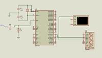
hello amit, sorry again for being late to reply... well as far as this circuit diagram is concerned,it is correct..i don't think that you need an extra max232(other members please correct me if I am wrong), you just needs to connect your modem through its tx,and rx pins to corresponding rx and tx pins of your mcu. now with your code, I don't think there is any problem, you might be just missing few connections. I am posting here two pictures of the proteus design on which I checked your code,one is showing connections and the other is taken during run and is showing the actual commands that are being send to modem by microcontroller(through virtual terminal) during run.
tell me which company's phone are you using? if nokia, then please install ovi suite before testing your code through your phone's modem and if any other company's then too, install corresponding software package as pc recognizes phone modems through these softwares. good luck


- - - Updated - - -

and you too,please upload the picture of proteus design on which you are trying to run your code :)
 

Status
Not open for further replies.

Part and Inventory Search

Welcome to EDABoard.com

Sponsor

Back
Top