Continue to Site

Welcome to EDAboard.com

Welcome to our site! EDAboard.com is an international Electronics Discussion Forum focused on EDA software, circuits, schematics, books, theory, papers, asic, pld, 8051, DSP, Network, RF, Analog Design, PCB, Service Manuals... and a whole lot more! To participate you need to register. Registration is free. Click here to register now.

[SOLVED] how to convert AC to DC forinput to ADC

Status
Not open for further replies.

moonnightingale

Full Member level 6
Full Member level 6
Joined
Sep 17, 2009
Messages
362
Helped
5
Reputation
10
Reaction score
5
Trophy points
1,298
Activity points
3,832
I am having 40 VAC. I want to give it to input of ADC of micrcontroller. Bue the ADC can have the maximum input of 5 V.
Soi used the voltage divider and limited 40 VAC to 5 VAC but now the problem is that ADC needs DC Voltage.
How to convert this VAC to 5VDC
Plz help
 

What do you mean by 5V AC is this RMS?
You have to attenuate the voltage to about 5v peak to peak and then add an offset of 2.5v so that it becomes 0 to 5 instead of +-2.5

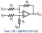
You can use a differential amplifier to add the offset
DiffAmp.jpg
 
I am designing in proteus
My end output coltage is 5 VAC.
I have to feed in this voltage to ADC
I think i cannot give AC volt to ADC then how can i convery AC to DC
 
I repeat, the only difference between AC and DC is that the AC swings from minus voltage to positive voltage, if you have a sinusoidal of 5v peak to peak then the swing is from -2.5v to +2.5v, if you add a DC offset of 2.5v then the swing becomes -2.5v+2.5v (which results to 0v) to +2.5v+2.5v (which results to +5v) where +2.5v is the offset.

in the schematic of my previous post feed the AC input to V2, V1 to GND and Vr to +2.5v.
If you don't want gain then set all resistors to 1K
 

The question says that
"The MC68HC12 input cannot exceede 5 volts, so a signal conditioning circuit is required so that that it can be fed to microcontrloller

I was having 40 Volts AC. I limited it to 5 volts through Voltage divider. Now this is 5 VAC.
Now can i give this 5 VAC to ADC of microcontrller or i have to first convert it to DC
 

It depends what you want to do, you can either rectify the voltage so that it becomes a straight line DC or you can add an offset to the AC so that the swing is positive above 0 and then insert in the ADC input.
 

So one thing is sure we always need to give DC voltage to ADC of MCU. Ami right in saying this
Can u help me how to rectify this in proteus. Can u send me design for making my AC to DC.
 

I want to convert AC to DC

Hi i am having a circuit which is giving output at R2 is AC which is from +2.5 to -.25
I want to add DC offset of 2.5 init to make it from 0 to 5 Volts
I am attaching the proteus file

Can somebody help me to make my AC to DC

Thanks

Can you please keep posting in the same thread instead of starting new ones with the same content... Threads merged [alexan_e]
 

Attachments

  • file.zip
    14.7 KB · Views: 170

the circuit to add the offset is like the one I have described in the previous post

Add_offset_to_AC.gif

I have used a rail to rail opamp to be able to get 5v output from 5v supply or else you will need a higher supply for the opamp

Alex
 

can u kindly send me design file.
thanks a lot

and also kindly explain me this circuit as well
 

The circuit I have added is just a differential amplifier as shown in post #2, the output is calculated using the formula also shown there, all I did was to add 2.5v to Vr as offset

Alex
 

I want to have +2.5 to -2.5 accross R2 which will later converted into 0 to 5 Volts

How can i adjust the settings such that i get +2.5 to -2.5 at R2


Ok is the first part of my circuit right where i am using concept of voltage divider
somebody told me to add capacitor in it to cater for spikes

where i have to insert capacitor
 
Last edited:

Ok this problem is solved of 2.5 Volts

just explain me functions of all resistors of Opamp circuit
 

Attachments

  • actodc_offset.zip
    16.8 KB · Views: 159
Last edited:

Your input is +-40 (80v peak to peak) so 40-2.5=37.5v
2.5v/37.5v=0.0666 , if R1 is 10000 ohm then R2 should be 10000*0.0666=666 ohm

so if you use R1=10000 and R2=666 you will have the 40 peak to become 2.5 peak

ro check use VR2= Vin * R2/(R1+R2) =Vin * 666/ (10000+666)= Vin * 0.0624
if Vin=40 then R2=40v * 0.0624 = 2.496v

Alex

PS, I didn't do 666 on purpose :evil:

Yes i also did the same way and the answer comes exactly 2.4 provided we have not installed circuit for differential amplifier
once we install that circuit, then the result at R2 is not from +2.5 to -2.5
Is it ok as it is impact of additional circuit

---------- Post added at 19:55 ---------- Previous post was at 19:50 ----------

why R 7 and R6 are 2 K
rest are 1 K
Can u give me some website where this differtial amplifier is explained in detail along with its components
 

yes the divider ratio changes because it is loaded by the diff amp circuit.
one solution is to use higher resistance in the opamp like 22k or lower resistance in the input divider or both.
The other solution is to use the diff amp as an attenuator, if you use R3=R4=10K, R5=666, R6=R7=1332 (these are twice R5 for balance) then the output will be 0 to 5 (almost)

If you do a search for differential amplifier you will find many articles, for example
Op-amps - The Differential Amplifier (Voltage Subtractor)
Operational amplifier applications - Wikipedia, the free encyclopedia


Alex
 

From one of the Forums i got this answer

Better is to divide the 80 Volt signal down with a resistor divider (e.g. 18K
and 2K); have a second resistor divider of equal resistances (e.g. 3.9K)
to give the ADC a 2.5v offset, then couple the two dividers with a
capacitor. With this scheme spikes on the 80 signal go through the 18K
resistor so there is more protection for the ADC input.


Can u draw this for me and explain me that is he correct while saying this
 

The described circuit is a letter H schematic, the two I in the sides are voltage dividers (two resistors in series each) and the - in the middle a capacitor which connects the two dividers.

Alex
 

Status
Not open for further replies.

Part and Inventory Search

Welcome to EDABoard.com

Sponsor

Back
Top