Continue to Site

Welcome to EDAboard.com

Welcome to our site! EDAboard.com is an international Electronics Discussion Forum focused on EDA software, circuits, schematics, books, theory, papers, asic, pld, 8051, DSP, Network, RF, Analog Design, PCB, Service Manuals... and a whole lot more! To participate you need to register. Registration is free. Click here to register now.

Is there a method to derive time constant of multiple RC circuits??

Status
Not open for further replies.

pannaguma

Junior Member level 1
Joined
Sep 27, 2009
Messages
18
Helped
0
Reputation
0
Reaction score
0
Trophy points
1,281
Activity points
1,441
Hi friends,

I have been preparing for competitive exams and came across a question on multiple RC circuit time constant derivation...
one particular problem was of the form:
----------R1||C1----------- <------------Vout+
|
|
R2||C2
|
|
---------------------------- <-------------Vout-
input was a DC voltage source I think, assume it parallel to R2||C2...

Now I did a little bit of searching and found this
So I gave a try and followed the same procedure, ie of finding thevenin equivalent of the circuit across the output terminals.

Shorting input voltage source, gives R1, C1, R2, C2 all in parallel with Vout, giving a time constant of [(C1+C2)*(R1*R2/(R1+R2))].

Is this correct? If not can some one please give me hint where I am going wrong?

Thanks for reading, appreciate any sort of help
 

Hi,

is this a two-port whose input is a voltage in parallel with R2||C2 and the output at Vout+ and Vout- ?
In that case, R2||C2 has no effect because it is in parallel with a voltage source.
And if there is no load, R1||C1 has no effect because there is no current flowing across it.
So, in that case, Vout=Vin. Right?
Regards

Z
 
Apart from what zorro said, if your input is a DC voltage source, as you say in your post, why at all you care about the time constant?
 
sorry guys, i typed the circuit correctly, but the white-spaces I inserted were ignored and the circuit was displayed incorrectly (which I failed to notice, sorry again)

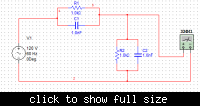
this is what I meant:

the outputs are same as those of the multimeter take off points...

@sutapanaki - yes you have a point there, I actually don't recall what source was given, maybe it was AC....

@zorro - don't recall anything being said about a 2 port network, it simply had a multiple RC circuit with a point called Vout...

sorry folks for the trouble, but any hints this time round? and yes please ignore the actual R/C values, I am just keen on knowing the time constant derivation in terms of R1, C1, R2, and C2... and whether my attempt was right...
 
Last edited:

Hi Pannaguma,

it is clear now!
Your thinking is right.
The time constant is [(C1+C2)*(R1||R2)] .

Let me give some remarks (I hope this will not produce confusion):

a) In general, a circuit with two energy-storage elements has two poles (two time constants). But in this case there are two C's but only one pole, because they are not independent: the purely capacitive mesh restricts one degree of freedom. So, there is a single pole (a single time constant).
b) There is a zero too, given by R1 and C1 [s0=-1/(R1*C1)].
c) If R1*C1=R2*C2, the zero and the pole cancel. In that case, Vout/Vin=R2/(R1+R2)

Regards

Z
 
This circuit is sometimes called frequency independent voltage divider when the condition zorro pointed out in c) is met. As far as I know it is used in oscilloscopes' input for wider BW.
 
thanks guys for the help
@zorro - can you suggest any textbook where I can read further on the pole-zero concept with respect to energy storing elements in circuits?
 

I cannot see why the shown circuit should have one single time constant.
What is its definition ?
How did you arrive at the expression T=(C1+C2)*R1||R2 ?

The transfer function is easily derived:

H(s)=(R2+sR1R2C1)/(R1+R2+sR1R2(C1+C2)).

Thus, we have a zero and a pole. Both cancel each other for equal components.
Therefore, it is - as mentioned already - a frequency compensated voltage divider 1:2.
That's all I can say to describe the circuit.

Addendum: Of course, if the 4 parts are not equal (that means: pole and zero do not cancel each other) you can measure the step response - and from this we can derive something like a "common time constant". But the problem is: For R1=R2 and C1=C2 this time constant has a finite value - but the circuit behaves like a resistive divider (without rise time).
 
Last edited:

This circuit is sometimes called frequency independent voltage divider when the condition zorro pointed out in c) is met. As far as I know it is used in oscilloscopes' input for wider BW.
Yes. Standard attenuating oscilloscope probes have this configuration (actually they can include more components for better compensation, but the basic configuration is like that). The screw that you adjust for the compensation of the probe changes one of the capacitors of the divider.
When the probe is correctly compensated you see that the edges of the square wave test signal reach the top without overshoot nor with the contrary effect.
Regards

Z
 

thanks guys for the help
@zorro - can you suggest any textbook where I can read further on the pole-zero concept with respect to energy storing elements in circuits?
I don't feel I can suggest a specific book. A good book on circuit theory should cover the subject you mention.

Nevertheless, there is a couple of (old!) books that helped me to learn very insightful concepts about:
1) how to find the location of poles and zeros in circuits (involving active and passive components) "by inspection", i.e., without need to completely solve it
2) how to find approximate (rather exact) expressions of poles and zeros in staightforward ways

The books are:
a) Electronic Principles, by Gray and Searle
b) Two volumes (3 and 5) by the same authors included in the book series of the SEEC

I hope I can answer to LvW's post later. (Sorry.; I can't now.)
Regards

Z
 

Hi again!

I cannot see why the shown circuit should have one single time constant.
Circuit theory learns that the number of state variables (or the number of poles) of a circuit is equal to the number of energy storage elements (C's and L's), minus the number of purely capacitive meshes, minus the number of purely inductive nodes.
N.B.:
1) A purely capacitive mesh can inlude voltage sources; a purely indictive node can inlude current sources.
2) That count include poles at infinity

The reason relays in the fact that each V on a C, or each I across an L, is a state variable. But if you have a mesh with several C's and voltage sources, the V on one of the C's can be determined from the V's on the ither C's and the voltege sources: so, it is not independent and there is one less independent state variable. (The same apply for indoctive nodes.)

In Pannaguma's circuit, there are 2 capacitors and 1 fully capacitive mesh, then one pole.

What is its definition ?
There can be different definitions, depending upon the context (signals, two ports...). We could look for precise definitions, but in this context (two-ports) i'd try something like this:

A real LTI circuit has natural responses of the form exp(-t/tau) and exp(-t/tau)*cos(w*t+phi).
(The first form corresponds to real poles, the second to complex conjugate pairs.)
In both cases, each tau is a time constant of the circuit.

How did you arrive at the expression T=(C1+C2)*R1||R2 ?
"Deactivating" the voltage source (i.e. putting V=0, i.e. in short-circuit), the two C's are left in paralel and the two R's as well. The characteristic response (an then its time constant) is that of a single RC with the total C=C1+C2 and the total R=R1||R2.

But the problem is: For R1=R2 and C1=C2 this time constant has a finite value - but the circuit behaves like a resistive divider (without rise time).

The response of this circuit to a unitary step is a step of amplitude As plus an exponential response of amplitude Ae [i.e. Ae*(1-exp(-t/tau)].
The amplitude of the step is determined by the capacitive divisor: Ae=(1/C2)/[(1/C1)+(1/C2)]=C1/(C1+C2).
The amplitude in steady-state is As+Ae, and is determined by the resistive divisor: As+Ae=R2/(R1+R2).
From the two equation above, it can be seen that if R1*C1=R2*C2 then Ae=0. This means that the amplitude of the exponential part (with constant time RC) is 0. For other conditions, in has a positive or a negative value (corresponding to the situations of overcompensation or undercompenstion of the oscilloscope probe mentionned in post #9).


Regards

Z
 

Quote zorro:
There can be different definitions, depending upon the context (signals, two ports...). We could look for precise definitions, but in this context (two-ports) i'd try something like this:
A real LTI circuit has natural responses of the form exp(-t/tau) and exp(-t/tau)*cos(w*t+phi).
(The first form corresponds to real poles, the second to complex conjugate pairs.)
In both cases, each tau is a time constant of the circuit.


Zorro, sorry but I cannot follow you. The expression exp(-t/tau) applies to a first order circuit and the asscociated time constant. But the circuit under discussion is NOT of first order.

Qote Zorro: "Deactivating" the voltage source (i.e. putting V=0, i.e. in short-circuit), the two C's are left in paralel and the two R's as well. The characteristic response (an then its time constant) is that of a single RC with the total C=C1+C2 and the total R=R1||R2.

No, the response is not and cannot be that of a single RC combination. There is an amplitude step at t=0 (as mentioned by you later) caused by the input capacitor.
Your view and the respective conclusion is not correct. You are not allowed to speak about a series or a parallel connection of elements if there is no input. You arbritarily have chosen the midpoint as a reference to deduce: Both R's and both C's act in parallel. But this assumption leads to false conclusions.
Example: Assume the two elements L and C have one common node and the two other ends are grounded. Series or parallel tuned circuit? Cannot be answered without defining the input.
For input at the common node they act parallel -and for an input at one of the grounded nodes the are in series.
__________
Finally, you can convince yourself that numeric calculation of the time constant given by you in no case (in particular for equal time constants of the respective RC pairs) matches simulation results. But that's no surprise: For the given circuit it is not appropriate to characterize it with a single time constant.
 

As a side remark, I neither understand where the term "purely capacitive mesh" applies in the discussed circuit, nor what would be a commonly agreed meaning of this term.

If I understand right, there are no doubts about the circuit's transfer function derived by LvW, also about the existence of a pole and a zero. Depending on the R and C values, they act either as lead-lag or lag-lead circuit, or cancel exactly.

In think, it's common practice to designate poles and zeros by characteristic frequencies, respectively time constants. So obviously, in the general case, the circuit's transfer function can be characterized by two time constants.

Zorro however derived a third time constant T=(C1+C2)*R1||R2. It actually exist in the circuit, but not in the transfer funtion, it can be seen in the circuit's output impedance.
 
I think by "purely capacitive mesh" zorro means a purely capacitive voltage loop, which we have in the circuit.The time-constant (C1+C2)*R1||R2 is also there in the transfer function LvW posted. It has to be, this is the natural frequency of the circuit. If you take R1+R2 outside the brackets in the denominator, you get that time-constant. So, circuit is 1st order, but has 2 time-constants - one for the zero and one for the pole.
 

There's only one time constant.

Following the expression given by LvM


H(s)=(r2+sr1r2c1)/(r1+r2+sr1r2(c1+c2))​


Expanding in single fractions


H(s) = A0 + A1/(1+sB1)​


with


A0 = c1/(c1 + c2)
A1 = (c2r2-c1r1)/((c1+c2)(r1+r2))
B1 = r1//r2 (c1 + c2)​


More general:

Every H(s) = P(s)/Q(s) = SUM( Ak/(1+sBk) )

with Bk = poles of Q(s)

Then, each time constant is Bk when the pole is real and the real part when is complex conjugate.
 
The time-constant (C1+C2)*R1||R2 is also there in the transfer function LvW posted.
Right, it's the time constant related to the pole.
There's only one time constant.
You showed that the zero/pole combination can be factorized into a sum, involving only a single pole. That's nice, but doesn't change the fact, that the rational transfer function has a zero with a characteristic frequency and a respective time constant. And, at least in my view, the rational form eases an intuitive understanding of the circuit's behaviour.
 
You showed that the zero/pole combination can be factorized into a sum, involving only a single pole. That's nice, but doesn't change the fact, that the rational transfer function has a zero with a characteristic frequency and a respective time constant. And, at least in my view, the rational form eases an intuitive understanding of the circuit's behaviour.

But imho due the zeros have no effect on the transient fading is not correct to call these coefficients time-constant.


For example, F(s) = (1-as)/(s(1+bs)) = 1/s - (a+b)/(1+bs) have a zero at a,

But the inverse laplace of F(s) is:
f(t) = h(t) - (1+a/b) e^(-t/b) --> a has no effect in the decay rate.
 
Last edited:
It is correct to say that the natural response of the circuit is defined by the pole and the associated time-constant. The zero is part of the transient response to a step input but does not affect the subsequent exp. decay. In the concrete circuit here, the initial jump of the output voltage to c1/(c1+c2) is due to the presence of the zero and the subsequent exp transition to r2/(r1+r2) is due to the pole. Zeros indicate singularities in the s plain as well as poles do. But only poles define the natural response in time domain.
 
Last edited:
  • Like
Reactions: zorro and LvW

    LvW

    Points: 2
    Helpful Answer Positive Rating

    zorro

    Points: 2
    Helpful Answer Positive Rating
Hi,

Let me try to clarify some points. I will highlight some words inside the quotes.

Quote zorro:
There can be different definitions, depending upon the context (signals, two ports...). We could look for precise definitions, but in this context (two-ports) i'd try something like this:
A real LTI circuit has natural responses of the form exp(-t/tau) and exp(-t/tau)*cos(w*t+phi).
(The first form corresponds to real poles, the second to complex conjugate pairs.)
In both cases, each tau is a time constant of the circuit.


Zorro, sorry but I cannot follow you. The expression exp(-t/tau) applies to a first order circuit and the asscociated time constant. But the circuit under discussion is NOT of first order.

I didn't told about first order circuits. I said that natural responses had the mentioned forms.
A "natural response", "characteristic response" or "natural mode" is a waveform that can be found in the circuit when no input is applied. If we think in a passive network, it is originated by the energy initially stored in C's and L's.
Natural responses are related to the poles of the circuit.
If the circuit is real, its poles are real (first case) or form conjugate pairs (second case).
Each real pole is responsible of a natural mode of the circuit, of the form exp(-t/tau).
Each complex conjugate pair is responsible of natural modes of the circuit, of the form exp(-t/tau)*cos(w*t) and exp(-t/tau)*sin(w*t), whose combination with any amplitudes can be expressed as exp(-t/tau)*cos(w*t+phi).
In both cases, -1/tau is the pole or the real part of the pair respectively.
A circuit can have many time constants.
For this I wrote that In both cases, each tau is a time constant of the circuit.

(Let's not mention the case of multiple poles, in which case there are also natural responses of the form t^n*exp(-t/tau), n ranging up to the order of multiplicity minus 1.)

But, by the way, the circuit under discussion IS of first order, as clearly shown by the transfer function.

Qote Zorro: "Deactivating" the voltage source (i.e. putting V=0, i.e. in short-circuit), the two C's are left in paralel and the two R's as well. The characteristic response (an then its time constant) is that of a single RC with the total C=C1+C2 and the total R=R1||R2.

No, the response is not and cannot be that of a single RC combination. There is an amplitude step at t=0 (as mentioned by you later) caused by the input capacitor.
Your view and the respective conclusion is not correct. You are not allowed to speak about a series or a parallel connection of elements if there is no input. You arbritarily have chosen the midpoint as a reference to deduce: Both R's and both C's act in parallel. But this assumption leads to false conclusions.
Example: Assume the two elements L and C have one common node and the two other ends are grounded. Series or parallel tuned circuit? Cannot be answered without defining the input.
For input at the common node they act parallel -and for an input at one of the grounded nodes the are in series.

I didn't say that the response to a step has only an exponential part. I said that the characteristic response (other name of what is called natural response or natural mode) is that of an RC=(R1||R2)*(C1+C2). An that in the circuit under consideration the response to a step is a step plus exponential part.
LvW, please reconsider your statements, especially those highlughted in blue.

As I stated before, the natural responses of the circuit depend of the poles.
If you want to "see" a natural response (not a forced one), deactivate the inputs and look at how the circuit can evolve from some initial condition.
Deactivate a voltage soure means V=0 -> short circuit it.
Deactivate a current soure means I=0 -> open it.
So, the natural mode of a parallel LC excited by a current sourtce is the same that a series LC excited by a voltage source.

As I said, the response to a step of the circuit in question has two components: a step plus an exponential waveform. The step is not part of the characteristic response, but of the forced one. Instead, the exponential part will be present for any input, with an amplitude (negative, positive, or zero) that depends of the particular input applied and of the initial conditions (V on the C's at t=0 and -if there were- I across the L's) of the circuit.

Finally, you can convince yourself that numeric calculation of the time constant given by you in no case (in particular for equal time constants of the respective RC pairs) matches simulation results. But that's no surprise: For the given circuit it is not appropriate to characterize it with a single time constant.

I don't agree. Posts #15, 17 and 18 explain why.

_Eduardo_ said:
But imho due the zeros have no effect on the transient fading is not correct to call these coefficients time-constant.
Right!
A zero is not related to any natural mode.
A time constant if a RC branch is not necessarily a time constant of the circuit. The circuit under consideration is a good example.

Regards

Z
 
But imho due the zeros have no effect on the transient fading is not correct to call these coefficients time-constant.
I can agree to this viewpoint.
 
Status
Not open for further replies.

Part and Inventory Search

Welcome to EDABoard.com

Sponsor

Back
Top