Continue to Site

Welcome to EDAboard.com

Welcome to our site! EDAboard.com is an international Electronics Discussion Forum focused on EDA software, circuits, schematics, books, theory, papers, asic, pld, 8051, DSP, Network, RF, Analog Design, PCB, Service Manuals... and a whole lot more! To participate you need to register. Registration is free. Click here to register now.

[SOLVED] Full Bridge Inverter with MOSFET and IR2110 gate driver

Status
Not open for further replies.

adityo.kusumo

Newbie level 5
Newbie level 5
Joined
May 21, 2010
Messages
8
Helped
4
Reputation
8
Reaction score
4
Trophy points
1,283
Location
Indonesia
Visit site
Activity points
1,492
This is my first post here, i need help on my final year project to make a grid connected inverter.

For the full bridge inverter circuit i planned to use IRF2807 (75V Vds, 82A Ids) and Two IR2110 for the driver. I never use IR2110 before and failed many time when i want to make a H-Bridge for DC motor last year. Hopefully after asking you guys i can get enlightenment for my final year project.

I planned to design the circuit based on this sample project that i get from another website :

**broken link removed**

i have some question about the schematic since the specification is quiet different.

My DC input voltage is 34V (2 series solar panel), The power rating is about 100Watt so the MOSFET should able to drain about 10A max current. The output of the inverter will be connected to 18V - 220V step up transformer. My controller will use hysteresis current control method so the switching frequency is not fixed and varied up to 100kHz.. and i want to isolate (different ground) between my micro controller and power circuit. How can i use the optocoupler to isolate it? is there any optically isolated buffer since i planned to use buffer (micro controller (ATmega 8535, 16MHz -> Buffer IC -> Optocoupler -> IR2110)

Based on my specification, is there any component that i should change? i read before to change the diode to the fast recovery one, and change the resistor value..

i will appreciate any suggestion or critics, thanks in advance.. :razz:
 

Hi there...

If you have to isolate your ground, I would recommend you to use isolation transformer
instead of optocoupler. In this, you will no longer need to use high-side capable driver ICs,
you will instead use a small gate drive transformer, buffered by the totem-poles.
The transformer is very easy to wind, use small toroid core, about 10mm
outer diameter or even slightly smaller. Make sure that it will not saturate.

See the schematic below...
Just make sure that you follow the polarities, you already know that of course.:grin:
Feel free to ask if you have further questions.

 
Last edited:
Hi there...

If you have to isolate your ground, I would recommend you to use isolation transformer
instead of optocoupler. In this, you will no longer need to use high-side capable driver ICs,
you will instead use a small gate drive transformer, buffered by the totem-poles.
The transformer is very easy to wind, use small toroid core, about 10mm
outer diameter or even slightly smaller. Make sure that it will not saturate.

See the schematic below...
Just make sure that you follow the polarities, you already know that of course.:grin:
Feel free to ask if you have further questions.


Thanks for your answer ferdinand, may i know why you recommend me to use isolation transformer instead of optocoupler? is there any problem that i will face if i use the optocoupler? Honestly your suggestion is quiet new for me, i never read this kind of gate driver. Since my deadline is less than 2 month i think i wouldn't try to gamble for trial and error. But i still curious about the winding ratio of the transformer and will it function well on the high frequency (up to 100kHz).

But still i still prefer to use optoisolator for now, it's much simpler for me but i don't know what type of optoisolator that i should use and is there any other component that i need to use along with the optoisolator.

Thanks.
 
Using the transformer is much simpler in my opinion.
If you can find a toroidal core, give me the part number
and I will provide you the number of turns including the
calculations. 100kHz is already high that's why I recommended
gate drive transformer.

Don't worry, I already used this method of driving
many times. It's easy to do if you have the materials.
Less parts than the optocoupler and is also cheaper.
 

If you use the IR2110's, I would recommend that you reduce the gate resistors (R1 to R4) to something around 10R to 33R. Also add a 1k resistor between the gate and source of each MOSFET.

Hope this helps.
Tahmid.
 
Using the transformer is much simpler in my opinion.
If you can find a toroidal core, give me the part number
and I will provide you the number of turns including the
calculations. 100kHz is already high that's why I recommended
gate drive transformer.

Don't worry, I already used this method of driving
many times. It's easy to do if you have the materials.
Less parts than the optocoupler and is also cheaper.

Thx for your answer, but since this is my final year project i depend on my lecturer decision, and he said to use optocoupler for isolation. But i still don't know what type of optocoupler that could work in high bandwidth and pretty common so i could find it easily on my Country. Is there any suggestion for the optocoupler type?

If you use the IR2110's, I would recommend that you reduce the gate resistors (R1 to R4) to something around 10R to 33R. Also add a 1k resistor between the gate and source of each MOSFET.

Hope this helps.
Tahmid.

Thanks for your answer Tahmid, do you mean by 10R to 33R is 10 Ohm to 33 Ohm? oke i will add 1k resistors between MOSFET's gate and source. Is there anything else i should change? How about the diode type?
 

The diodes are fine. For gate resistors use any value of resistance between 10 ohm and 33 ohm. Just make sure that all four of them have the same value.

Hope this helps.
Tahmid.
 
Hello all, last night i tried the IR2110 gate driver with IRF3205 MOSFET and make a half bridge circuit for testing.. here are the schematic for the test circuit :

59673d1312428064-skematik-tanpa-mikro.png


it goes well when i push on-off the Hin with a switch, the low side MOSFET is always ON so i connected the Lin directly to the 12V supply. The DC motor could run when the switch ON for about 4 second if i keep push the Sw1 (until the boostrap capacitor run out). And if i periodically push and release the push button (to generate handmade PWM) the motor keep running..

The problem come up when i want to control the PWM with my microcontroller (ATmega8535). The schematic are below :

59674d1312428094-skematik-dgn-mikro.png


Still, the Lin is directly connected to vcc (5V) from microcontroller power suppy so it should always ON, and the Hin is connected to pwm signal generated by the microcontroller. When i power up the circuit the motor run slowly (much slower than before) but when i touch the Drain of the high side MOSFET with my finger and my foot is on the floor the motor runs as it should run, but when i pull up my feet from the floor the motor run slow again. Then i realize i haven't connect the gnd from the microcontroller to power circuit GND. But when i connect the gnd (from uC) to GND (from power circuit), the motor totally shut down..

i think the problem is in grounding or i confused how to use two different power supply to run the circuit..

can you help me to see is there anything wrong from my circuit? Thx..
 

Attachments

  • skematik tanpa mikro.png
    skematik tanpa mikro.png
    32.9 KB · Views: 4,826
  • skematik dgn mikro.png
    skematik dgn mikro.png
    34.9 KB · Views: 3,988
Last edited:

Hi,
The signal coming from AVR is at 5v level. Connect pin 9 (VDD) to +5v instead of 12v. Then I think it should work fine. Change R1 and R2 from 220 ohm to 22 ohm or as I suggested before, anything between 10 ohm and 33 ohm. Also connect a 1k resistor from gate to source of the MOSFET.

Hope this helps.
Tahmid.

Hello Tahmid, i forget to mention that i have tried it too before (connect the pin 9 to the 5V instead of 12V) but it didn't work. After read your reply and re-reading the datasheet i found this typical connection at the datasheet :

59708d1312473028-typical-connection.png


and then i changed the circuit base on your reply and the typical connection into this :

59709d1312473078-schematic_v3.png


the circuit consist of 3 separate power supply :
1. vcc (5V) & gnd from the uC board
2. 7.4V Li-ion batt for the motor supply
3. 12V from the power supply

it works just fine and i able to control the motor speed with PWM (5V) that generated from my microcontroller. And when i connect the 1k resistor between gate and source of each MOSFET, the motor run strangely. The motor seems to run and stop periodically even the PWM is on the high duty cycle. when i disconnect the resistor the motor run normally.

the most strange problem that i face now is when i disconnect all 3 power supply from the circuit and try to run it again, it just do nothing. The motor won't run until change the circuit with 12V on VDD, Lin, and Hin. After i do that (run the motor for a while) i able to control the motor with 5V vdd, 5V Lin, and PWM (5V) to the Hin. i have no idea what is going on, is it from the improper capacitor value?
 

Attachments

  • Typical Connection.png
    Typical Connection.png
    72.6 KB · Views: 3,503
  • schematic_v3.png
    schematic_v3.png
    39.4 KB · Views: 3,329

Hi,
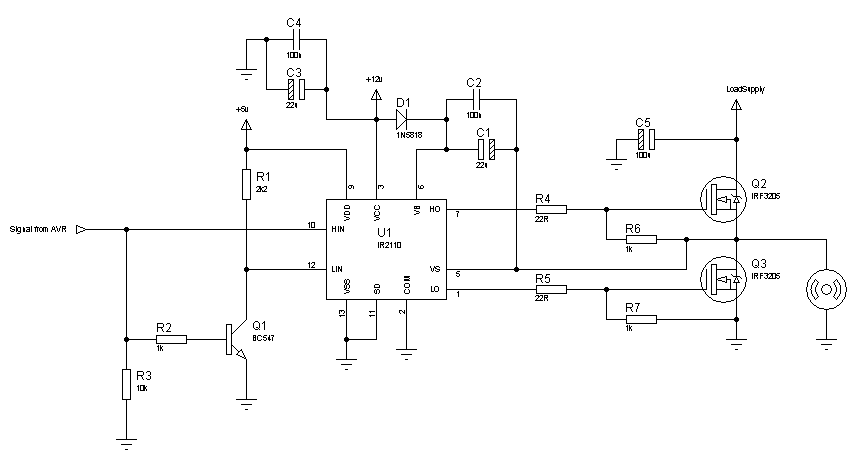
You have to use a fast switching diode at the bootstrap. So, switch to 1N5818 as the first diagram shows. Try with this circuit, I think this should work:
70_1312784222.png


Hope this helps.
Tahmid.

---------- Post added at 12:19 ---------- Previous post was at 12:17 ----------

C1, C3 - 22u
C2, C4 - 100n
C5 - 100u
R4, R5 - 22R
The rest of the resistors are in kilo-ohms.

Hello Tahmid, thx for your response. Actually, i gave up trying with VDD 5v, so i decided to use vdd = 12V and convert my PWM level to 12V with hex buffer (use pull up resistor to 12V) and with those configuration i able to modulate the load supply voltage with PWM from my micro controller.. i'm done testing with half bridge configuration in my breadboard and now i just started to build up the full bridge configuration in my breadboard. Hopefully it goes well, i follow the schematic from circuit project so there is no NOT gate in the circuit. i'm afraid there will be short period that both of my high and low MOSFET ON and get short circuited. I don't know how to make the dead time between switching (hope you know what i mean) so i plan to use simple delay_us or delay_ms function to make sure all the switches are in OFF state before proceed to the next cycle.

btw, i have problem simulating my circuit in ISIS proteus, i didn't find IR2110 IC in the library. there's only IR2112 so i try to use it. here's the schematic :

59912d1312789451-isis.png


do i have to change the hidden pins connection? i found that the VSS pin of the IR2112 connected to vcc in default. it should connected to gnd right? but i tried both and the circuit still doesn't work. Can you help me? and is there any way to get IR2110 in my library? Thx
 

Attachments

  • isis.png
    isis.png
    28.9 KB · Views: 3,329
Hi,
Not 100% sure, but I think, when using a high-low side driver, both high side and low side MOSFETs can not be on at the same time. So, that may be your problem as LIN is connected to VCC. I'm also not sure if Proteus simulates high-low side drivers properly. I'd suggest that you try the circuit practically on a bread board. I still suggest that you try the circuit I posted, once. When you have it working and you play with it, I'm sure many of your doubts and questions will be cleared and answered.

Also, in the schematic, you didn't put any resistor between the AVR pins and the LEDs. Remember to add them.

Hope this helps.
Tahmid.

I tried to simulate with along try it on the breadboard. And yesterday i succeeded to invert 7.4V DC voltage into AC.. Thanks for your help..

The ATmega8535 generating PWM, breadboard circuit of Full Bridge Inverter
59937d1312850931-1-breadboard.jpg


Output of the inverter, still in low switching frequency
59938d1312850948-2-inverted-low-frequency.jpg


Output of the inverter, trying high switching frequency up to 20kHz
59939d1312850964-3-inverted-high-frequency.jpg


now currently i designing my PCB with altium for this project. Btw, i read in the datasheet that 1N5818 reverse voltage rating is only 30V. I planned to use 36V DC voltage for my inverter. Do i need to change the diode? Is there other diode that have similar characteristic with 1N5818 but with higher reverse voltage rating?

About the proteus, do you have any fullbridge inverter simulation file that i can modified to simulate my circuit? it don't have to use IR2110, maybe with some optocouplers for the gate driver?
 

Attachments

  • 1 Breadboard.jpg
    1 Breadboard.jpg
    364.3 KB · Views: 3,440
  • 2 Inverted low frequency.jpg
    2 Inverted low frequency.jpg
    325.6 KB · Views: 3,242
  • 3 Inverted High Frequency.jpg
    3 Inverted High Frequency.jpg
    296.5 KB · Views: 3,166

Hi,
You can use any fast-recovery diode that can handle the maximum voltage of the circuit. I almost always use the UF4007 or BYV26(C/E) as these are quite common and cheap.
Maximum repetitive peak reverse voltage of:
BYV26C - 600V
BYV26E - 1000V
UF4007 - 1000V

I haven't managed to run any full-bridge properly on Proteus. Might be a problem in Proteus. Might be a mistake I made somewhere.

Hope this helps.
Tahmid.
 

I bought the same driver(IR2110), but I have a problem. HO is holding +V and it doesn`t change it if the input signal is low. Here is my sheme. Can you tell me where is the problem???
 

Attachments

  • sheme.jpg
    sheme.jpg
    59.9 KB · Views: 756

Connect a resistor between the gate and source of each MOSFET. Then connect a resistor (load) across the low-side MOSFET and test the output across the resistor and not the HO of the IR2110.

Hope this helps.
Tahmid.
 
I have connted extra resistors to GS and to lower transistor, but I was afraid of "BIG BANG" and i used 4.7k for GS and 6.8k for load. I have connectedd and extra capacitator between COM and Vcc as the datasheet said. Here is the new chartchart.jpg


Inspite of that something exploded. I think the transistors are OK. My question is are these resistenses enough or I must use smoller because I saw that the voltages on the exits of the driver are now very low. Thanks!
 

What is the voltage applied to the high side MOSFET?
I suspect that the IR2110 might have been damaged.
Check the diode D7 and capacitor C12 to see if they are okay. What is the voltage rating of the capacitor you used?
Where are the input signals to the IR2110 coming from? Can you post pictures of the waveform of the input signals. There might be cross-conduction between the MOSFETs. What is the frequency of the input signals?
I would replace R3 and R4 with 1k resistors but 4.7k is okay.

Hope this helps.
Tahmid.
 

C12 ana C13 are designed for 250V. For this experiment i don`t use any input signals- 0V for Low input and 0V for high input. The diod is Ok too. I think I`ve done something with the high voltage input because when I examined the PCB only the input terminal is dark. I`ll check the connections and I`ll try again. :)
 

Status
Not open for further replies.

Similar threads

Part and Inventory Search

Welcome to EDABoard.com

Sponsor

Back
Top