Continue to Site

Welcome to EDAboard.com

Welcome to our site! EDAboard.com is an international Electronics Discussion Forum focused on EDA software, circuits, schematics, books, theory, papers, asic, pld, 8051, DSP, Network, RF, Analog Design, PCB, Service Manuals... and a whole lot more! To participate you need to register. Registration is free. Click here to register now.

[SOLVED] please help==>74HC595

Status
Not open for further replies.

AliRazoR

Advanced Member level 4
Full Member level 1
Joined
Oct 26, 2010
Messages
115
Helped
4
Reputation
8
Reaction score
4
Trophy points
1,298
Activity points
2,001
hi

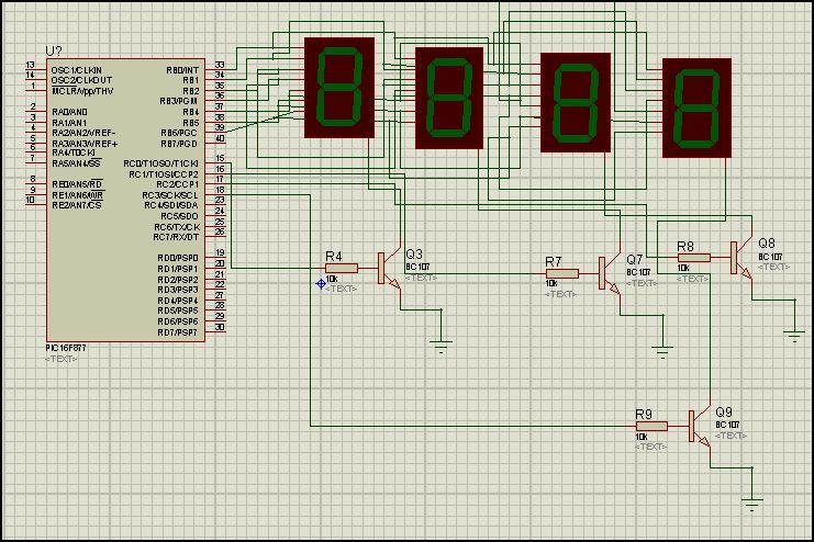
i want to connect 8 seven segments to pic 16F877 so i want to use 74HC595 IC, but unfortunately i dont have the code in C (MikroC) language.

or any other way that i can connect 8 seven segment to pic.(each seven segment should count down different number, so NO multiplexing method)

Does any one have the code?
please

Thanks in advance.
 
Last edited:

Hi,
If you have 8 seven segments, without multiplexing, it'd be impractical, requiring 8 ports. And 16f877 hasn't got 8 ports. A more practical method is to use 7 data lines multiplexed and control the anode/cathode of the 7-segments, either using 8 pins, or use 74hc595 or similar shift register using 3 pins.

Hope this helps.
Tahmid.

---------- Post added at 05:40 ---------- Previous post was at 05:39 ----------

I have a code with 6 7-segments that can easily be ported to 8 displays. What is your specific application?
I'm enjoying Eid and am not at home, I'll post the code once I go back home.
 
sorry i made a mistake,4 seven segment.if possible for you to give me the code,i really thank you man.

I am working on adaptive traffic light control system in this semester

BTW thanks for reply.
 
Last edited:

Hi,
I'll help with the code. Even for 4 seven segments you need to have them multiplexed.
 

how can i multiplex 4 seven segment?
each seven segment should be on, and counts down different number for traffic in each road.

sorry this my first project with pic and i do not know so much about different way.

i have 12 input from sensors, 12 output for red,green and yellow,so only afew pins left.:-(
 

This is a sample code:
Code:
sub function Send7(dim val7 as byte) as byte 'Common cathode
    select case val7
           case 0
                result = 63
           case 1
                result = 6
           case 2
                result = 91
           case 3
                result = 79
           case 4
                result = 102
           case 5
                result = 109
           case 6
                result = 125
           case 7
                result = 7
           case 8
                result = 127
           case 9
                result = 111
    end select
end sub
............
............
    disp[0] = d0
    disp[1] = d1
    disp[2] = d2
    disp[3] = d3
    for temp = 0 to 3
        PORTC = 0 'This is the port which has the common cathodes connected to it via transistor
        PORTD = Send7(disp[temp]) 'This is the data port
        PORTC.temp = 1 'RC0 = 1st display, RC3 = 4th display
        delay_ms(10) 'Delay between successive changing. If other stuff are to be done during this time, use timer for delay
    next temp

You should be able to adapt this to your requirement.
The code is in mikroBASIC.

Hope this helps.
Tahmid.
 
thanks for code, but i dont understand it.i only know mikroC.:(
 

Okay, I can help with translation.
select...case....end select is basically switch case
for temp = 0 to 3 is for(temp=0;temp>2;temp++){
} ie for ends at next
PORTC.temp means bit temp of PORTC
Code:
for temp = 0 to 3
...
next temp
is
Code:
for(temp=0;temp>2;temp++){
...
}
The rest are same.

Hope you understand now and that it helps.
Tahmid.
 

is not like this?
for(temp=0;temp<3;temp++){}
 

No, since, I would want temp to equal 3.
It could be for(temp=0;temp<4;temp++){}

Hope this helps.
Tahmid.
 

Hi,
d0 to d3 are the 4 values, ie, something between 0 and 9 that you want to display on the 7-segment,d0 for left-most, d1 for next and d3 for right-most.
disp[0] shows that disp is an array and 0 is the index no.
disp[1] shows that disp is an array and 1 is the index no.

Hope this helps.
Tahmid.

---------- Post added at 18:30 ---------- Previous post was at 18:29 ----------

Go to the mikroC help menu, click Help.
On the tabs in the help menu click Index.
Type in array. Select array from the menu and click it.
On the display area, you have complete details on arrays and how to use them in mikroC.

Hope this helps.
Tahmid.
 
i can not use this code in mikroC it gives error; PORTC.temp = 1

in mikroC we write portc.f0=1; or portc.f1=1; means RC0 and RC1 are high
 

unsigned short mask(unsigned short num) {
switch (num) {
case 0 : return 0x3F;
case 1 : return 0x06;
case 2 : return 0x5B;
case 3 : return 0x4F;
case 4 : return 0x66;
case 5 : return 0x6D;
case 6 : return 0x7D;
case 7 : return 0x07;
case 8 : return 0x7F;
case 9 : return 0x6F;
} //case end
}//~


unsigned short temp,disp[]={1,2,3,4},i ;
void main() {
adcon1=7;

//ansel=0;
//anselh=0;
INTCON = 0;
C1ON_bit = 0; // Disable comparators
C2ON_bit = 0;
PORTB=0;
TRISB=0;
portc=0;
trisc=0;

disp[0];
disp[1];
disp[2];
disp[3];
for(i=0;i<4;i++){
PORTC = 0 ;////This is the port which has the common cathodes connected to it via transistor
PORTb = mask(disp); ///////'This is the data port
//PORTC.f(i) = 1; ////////////////'RC0 = 1st display, RC3 = 4th display
PORTc |= (1<<i);
delay_ms(1000); /////////////'Delay between successive changing. If other stuff are to be done during this time, use timer for delay
}
}

I tried this code, but only one seven segment works.it shows on one seven segment 1,2,3,4


thanks so much for your help man.
 
Last edited:

Code:
disp[0];
disp[1];
disp[2];
disp[3];
What does this do? I'm not very good at C, so I don't know.
Change delay from 1000 to 10.

That's mostly the code. Now the hardware part of things, do you know how to connect it?

Hope this helps.
Tahmid.
 
disp[]={1,2,3,4}; //////////////////// number0,number1,..number 3

disp[0] ==> first number in disp[] ==> 1
disp[3] ==> 2'nd number in disp[] ==> 3


---------- Post added at 19:15 ---------- Previous post was at 19:12 ----------

i changed the delay to 10, it shows only number 4.

---------- Post added at 19:17 ---------- Previous post was at 19:15 ----------

i think most of problem is with this part,because this command enables the seven segments.(PORTB |= (1<<temp);)
 

Hi,
Can you see the outputs from RC0 to RC3 changing values, ie going from 0 to 1 to 0?

---------- Post added at 19:22 ---------- Previous post was at 19:20 ----------

Hi,
Instead of 4 7-segments as shown in the circuit, just use a multiplexed one for simulation purposes. Type in 7SEG-MPX4-CC. This would make the wiring much easier.
 
Status
Not open for further replies.

Similar threads

Part and Inventory Search

Welcome to EDABoard.com

Sponsor

Back
Top