Continue to Site

Welcome to EDAboard.com

Welcome to our site! EDAboard.com is an international Electronics Discussion Forum focused on EDA software, circuits, schematics, books, theory, papers, asic, pld, 8051, DSP, Network, RF, Analog Design, PCB, Service Manuals... and a whole lot more! To participate you need to register. Registration is free. Click here to register now.

12vdc to 230 vac inverter freewheeling diode burning.

Status
Not open for further replies.
Hi,

again, please read how LC filter work. I think it is important that you understand what you design. In every description you can see where the input is connected and the output.
Then you will see that the load must be connected to the Cs.
Only change the upper load connection to the upper node of the Cs, so that the load is in parallel to the Cs.

Klaus

:-(
I am sorry but i cant understand what you said,do you mean an LC filter at secondary, just before load is connected.
 

You are trying to knock down a square wave to a sine wave at 50 - 60 Hz. Big expensive inductor, you could try using a primary or secondary of a large iron transformer for the inductor.
 

Attachments

  • inverter output filter.JPG
    inverter output filter.JPG
    25.3 KB · Views: 101
You are trying to knock down a square wave to a sine wave at 50 - 60 Hz. Big expensive inductor, you could try using a primary or secondary of a large iron transformer for the inductor.

I have e25 bobbins for ferrite transformers, I can wind them with 20 swg copper, can I use them instead of transformer ?
 

I have e25 bobbins for ferrite transformers, I can wind them with 20 swg copper, can I use them instead of transformer ?

No, ferrite is for high frequency, It would take a HUGE ferrite core to have any effect on 50-60Hz
 
No, ferrite is for high frequency, It would take a HUGE ferrite core to have any effect on 50-60Hz

ok,I wonder what is done in older square ware inverters,to solve this problem.I think most of them are still square wave type.
 

ok,I wonder what is done in older square ware inverters,to solve this problem.I think most of them are still square wave type.

Yes, the older inverters Were square wave out. But it should be fairly easy to find an old iron transformer and just try one of the windings for an inductor. You will see the results right away on the oscilloscope.
 
There are no free-wheeling diodes used in this design. Remove them.
The voltage created should not exceed the Vds in this setup transformer which should have a 20:1 turns ratio and VA rated for your load. Since the drive is from switched current sources, the negative feedback into pin 1 is the control point for PWM regulation of the inverter.

This design would be overkill for just a 20W CFL as they operate on rectified line voltage DC, which you could supply instead of AC for your boost convertor using a small HF transformer instead of a steel core step up 50Hz type.
 
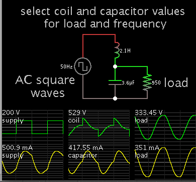
Here is a simple simulation, showing how a second order butterworth filter can turn a square wave into a reasonable sine wave, using the coil and capacitor values shown.

3754637400_1409841399.png


The load calculates to be 950 ohms (based on the 50 W figure mentioned earlier).
 
Status
Not open for further replies.

Similar threads

Part and Inventory Search

Welcome to EDABoard.com

Sponsor

Back
Top