Continue to Site

Welcome to EDAboard.com

Welcome to our site! EDAboard.com is an international Electronics Discussion Forum focused on EDA software, circuits, schematics, books, theory, papers, asic, pld, 8051, DSP, Network, RF, Analog Design, PCB, Service Manuals... and a whole lot more! To participate you need to register. Registration is free. Click here to register now.

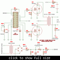
12vdc-220vac 100/200watts sinewave inverter

Status
Not open for further replies.
In order to Pure Sine wave in output wave, the PWM techniques are to be used. It is better to use sinusoidal PWM modulation techniques. The output of PWM inverter is a square wave, in order to obtain sinusoidal wave, the switching has to be such that the output wave has to be in multi stepped form whcih is similar to sine wave.
 

There is no need for any multi step wave form, your pwm has a variable duty cycle which will represent your final output,since there are high frequency signal in the wave then the low pass filter filter the high frequencies and allowing only the lower frequencies then you will see your sine wave signal.
 

hii..
i would like to know how modified sine wave inverter schematic will be der..
and is it good enough for using in ups min of 100watts
 

You can search my post I upload nice and simple modified sine inverter,its very simple and easy to build.
 

i would also like to know how the output waveforms are?? if u hav any practical one's...
and
is der any other modification that we can do instead of going for 17v battery which increases the cost involving??
 

You do not need a 17V battery. I made a mistake about the transformer voltage.
With a 220V to 12V transformer and the battery is charged to 13.2V the output of this inverter will have a peak voltage of 242VAC which is 171VAC RMS which is too low. The transformer should be 220V to 9.5V then the output will be 216V RMS.
 

thank u for ur response..
i think i should go for 220v to 9v transformer which are normally available...
and i m not getting why +12v of battery connected to 0v of center tapped transformer.sry if i m asking basic doubts

- - - Updated - - -

i am using this inverter in an ups and i m not getting how i should place battery charging circuit and cut-off circuit in the above
circuit....??
 

i think i should go for 220v to 9V transformer which are normally available.
Yes.

i m not getting why +12v of battery connected to 0v of center tapped transformer.
The transformer must be 18V center-tapped then one end is driven to ground and the transformer has 13.2V across half of the center-tapped winding so its output is +323V peak. Then the other end is driven to ground and the transformer output is -323V peak. 646V peak-to-peak is 228V RMS.

i am using this inverter in an ups and i m not getting how i should place battery charging circuit and cut-off circuit in the above
circuit....??
The inverter circuit uses an external battery charger. The inverter circuit needs an external circuit that detects low battery voltage then disconnects the load.
 
thanks for the info. sir!
can i find the output waveforms of CA3524 at pins 14 and 11?? And...
i want to see output waveforms of transformer.Help me ...!
 

The output signal at pin 14 and 11 should be square wave but when you connect the feed back you are controling the duty cycle of the signal this result to modified the signal to modified square wave also known as modified sine wave inverter,and issue of low battery ,overload protection and charging system has to be desinge and and attached saperately.
 
Is there anyway to feeding the output voltage back to CA3524 sense without using another transformer ???
and is there any possibility to feed back from primary of the output transformer??

- - - Updated - - -

In your schematic,the pin9 has only one capacitor of 10microfarad/16v attached to it.But in the datasheet of CA3524 he.s mentioned that we need to use a RC combination of capacitor value 1nF and 50k ohm potentiometer for AC stability.. Shall i modify it ??

- - - Updated - - -

And the feedback used is for the purpose of regulating the voltage i think...!!??Is it right..?
If yes,can we neglect it for the purpose of simplicity......??
 

Their are many inverters with different design,i saw many inverters with uses resistors from the final output and opto-isollator,while some other design tap it from drain-drain of the mosfet,and the feed back is used for controlling the output voltage by the means of sending feedback to control the duty-cycle,if you remove it you might have high voltage at the output depending of your transformer design and also you output signal will be square wave,so if you dont want to used the feed back control then your transformer should be 12-0-12 not 9-0-9.
 

I think i have got it sir! we need to use diodes(for protection purpose) from drains which are to be shorted and fed back..right sir???
and what is resistance that needs to be used in providing that feedback??Is that resistance should be VR1 to vary duty cycle??
what are voltage and current limits at pin1??and
is it safe for this inverter(providing feedback through drain to drain of mosfets)???
 
Last edited:

12vdc-220vac 100/200watts sinewave inverter.
Please read the PDF file IC Part Number!!!
 

Attachments

  • TDS2285.pdf
    589.1 KB · Views: 303

Status
Not open for further replies.

Part and Inventory Search

Welcome to EDABoard.com

Sponsor

Back
Top