Continue to Site

Welcome to EDAboard.com

Welcome to our site! EDAboard.com is an international Electronics Discussion Forum focused on EDA software, circuits, schematics, books, theory, papers, asic, pld, 8051, DSP, Network, RF, Analog Design, PCB, Service Manuals... and a whole lot more! To participate you need to register. Registration is free. Click here to register now.

12v DC Motor no control

Status
Not open for further replies.
Followed your instructions,
Disconnected resistor, still runs fast, joined to 5v supply, no change.
Shorted C and E motor stopped.
Changed transistor, motor still not running.
I did tests as on post #16, 4.6 volts at 9 and 8 on CYB8C.
Resistance between 4 and 8= 3.5ohms on 20K scale.
The voltage at led feed is 5v (orange), but there is also a voltage at all three light negative's, green=3.2. blue=4.8. and red=3.4. occasionally the blue light does flash.
The colour codes reading up are:- orange, purple, black, red, green, blue, brown, and pink.
 

Changed transistor, motor still not running.
After changing tansistor, did motor stoped perminently or it stops when resistor end connected to 5v or after this test passed you inserted resistance back in pcb, then it stops?
LEDs negative is pulled to ground through ic when processor gives a signal to lit the led. Is there any indication on dial what blue LED means.
 
I fully reassembled the circuit when switched on motor didn't run, so I then carried out previous tests.
I did test old removed transistor and it was faulty.
The light colours are green for fully charged battery, blue for half, and red for very low.
 

You have to confirm the driver stage is working ok by removing the resisor end as previosly mentioed. Motor should start running and when connected to 5v, it stops.
If this test pass ok then reinsert resistor end. As motor stops now it is heathy condition. Pin 9 of ic should have 5v, same as connecting externaly with 5v which were not previosly tested to be when tested with multimeter.
Now cosider the functions the processor which dont let motor to .
1. It checks current through FET.If it is very high or there is false signal to processor.
2. It checks for battery voltage. If it is in proper range, it lets motor to run and give indication to display the battery charge condition.
If battery is very low, now what. It will stop motor for protecting battery to over discharge.A false signal can do that also. So let check for that.
18_1315478879.jpg


46_1315479964.jpg

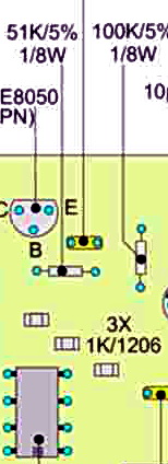
These two resistors 100k and 51k make 1/3 potential divider to change 12v to 4v for making it compatible with input of microcontroller. One end of 100k resister is connected to +12v and one end of 51k is connected with ground. The other ends are connected together and this point goes to pin 2 of processor.
Check around +4V on pin 2 of microcontroller.
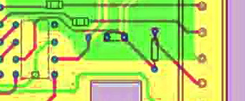
The third input to mcu is from pot. It is connected to pin 7 .
99_1315480886.jpg

Check it varies between 0-5v while rotating the pot. Be carefull avoid short circuiting while checking with multimeter prods.
 
Last edited:
Carried out all tests,
Things were normal at #9 with 4.88v, now for some reason lost that reading, motor still stopped but reading 0v.
(Didn't test by shorting b and c of S8050 transistor)
Checked voltage at controller #2, reads 3.88v
Reading at pin #7 while turning pot = 0v-4.88.
Thought maybe track broken for problem at #9, did tests and found that B's and E's now joined without any resistance on two transistors S8550 and S8050 under relay bottom of board.
The board tracks are now starting to break up, some repaired with wires.
 
Last edited:

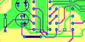
Now microcontroller can be suspected but check 54hc139 for more confirmation.Pin 5 and 6 of processor connected pin to 2 and 3.
46_1315515053.jpg

Cut them with sharp razer. Now connect small thin wires to pin 2 and 3
of 54hc139. Connect them with 5v , see results acordinglyThere are four posibilities of connectng
1. both connected to 0v-------pin4 led will lit.
2. 3 to +5 and 2 to 0v--------pin5 led will lit.
3. 2 to +5 and 3 to 0v-------pin6 led will lit.
4. both connected to +5v-----pin7 As no led is lid and pin7 is not connected anyware, this is idle state
Similarly pin 3 of processor is connected to pin 13 of 54hc 139. Cut this track and connect pin 13 to ground.Motor will start run. If these test pass ic and its related circuit is good.
 
Last edited:
Will carry out tests tomorrow,
Do you think there may be problem with transistors where I noted B and E joined with no resistance?
If you think there is problem will need to order S8550.
Thank you
 

Consider the resistance connected to pin 9 as test point for driver stage. When pulled out one side, Then tested with resistance end connected with nothing , motor stars running. and when connected to 5v motor stops as you tested and described in post #21. It is the input point of driver circuit. If this test pass, it means FET , three transistors and relevent circuit is working. Joining b and c will stop the motor. If motor is stoped then joining b and e will start the motor. This shorting test was for this transistor obove 54hc139. If you short other two transistors, they will be damaged.
Can you post some pics of upper and lower side of board and display dial.
 
Last edited:
Havn't make any progress today, tried to clean up board, basicly it's now losing tracking with heat, replaced both S8050 transistors, S8550 faulty ordered some for next week.
Tried another transistor with similar characteristics.
I think there must be break in track, there is 5v at regulater and at #16 and #8 on controller, but not at #9.
3.88 at #4 on controller.
Motor does not run.
Maybe best thing to do is make up secondary board wih transistors and chips.
 

Are you sugesting we finish trying to repair the controller?
I have other units I could use, just wanted to try and repair original if poss.
Maybe it's time to throw it away.
Have just changed all transistors (4). Also tried another chip HC139N.
Obsevations from today, motor not running, no voltage at #9 HC139N all other tests we've tried are positive.
Did tests from#26, item
1 = Red lit
2 = Blue lit
3 = Green lit
Cut track 13 on HC139 to 3 of processor, grounded 13 nothing happens, motor does not run.

Voltages from HC139n are:- 1,2,3=zero v, 4,5,6,=490v. 7,8,9,=zero v. 10,11,12=490v. 13=43v. 14,16,= 490v. 15=zero v.
 

No i think the only problem is if microcontroller is found damaged,even then we can bring this board to life by sumplimenting some other circuit in place of these ics. These references are just for information about motor speed control.
Readings of voltage level is ok.
If this reading is taken when track is cut, it can't be a true logic level. Pin13 will cause reverse logic level at pin 9. When it is hi, pin 9 will be lo and when it is lo, pin9 will be high which is driving 8050. But if pin 9 is at 0v(lo). s8050 is switched off, its collector goes to hi level and motor starts.
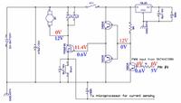
By tuching B and e with a metalic tweezer should let motor to run and touching b with c or c with e stops motor. I,ll post circuit diagram with voltages to measure for on and off condition.

See this portion of circuit.

90_1315694513.jpg
3_1315694513.jpg
14_1315694513.jpg


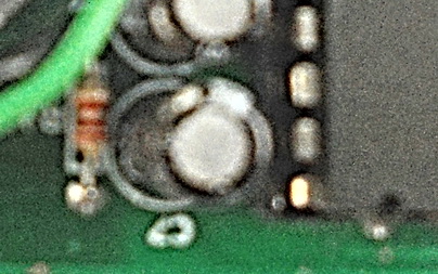
The diagramme whitch i have got, shows ( - )
of capacitor attached to resistor and pin 14 of ic
62_1315695190.jpg

and +ve to ground and then again to pin 16, which is positve. In this way +ve and _ve are shorted, which is not the case. The diagramme is drawn wrong in this portion. If you can trace with mutimeter by testing continuety.
This circuit around capacitor has nothing much to do. It only delays few miliseconds motor_run when initially power is applied to circuit letting it to stabilized.
But the control of motor through transistor leads and then by pin 13 should be established.
We can't short ouput but we can do this to input.Pin 9 is output and pin 13 is input.
We can also make secondary board.
 
Last edited:
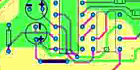
Checking and testing board -ive goes from capacitor to 15 one way, and through resistor to earth plate other way.
+ive from capacitor goes to 16 and 14, then to pin 8 of pot connector. Other way it goes through +ve of a capacitor, small capacitor and then to out pin of regulator.
Please see my attached very poor image.


img104.jpg
 

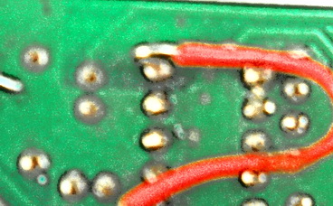
Ok ,that was the only possible confguration i was thinking of. When capacitor is charged through resister after a few ms. Then motor will be enabled to run. It is rather obvious that microcontroller is not working. Its inputs are reaching but it is not giving output. If there is somthing wrong with motor drive circuit, it should at least tun_on the LEDs to show battery condition. Somtimes it happens that there is a dry joint.Voltage are seen ok when checked from pcb side but when checked from top side on the ic pins, it does not reach there. Reconfirm the voltages on mc from top side from where the pins enter the plastic body of microcontroller. Taking -ve reding also from there from (pin 4) from top side.
It is a nice diagram you have made. at first glance, i thought you used some schematic software but it is hand drawn.
Sg3525 ic contains all the necessary circuits inside to drive FET directly with pot attached to control speed.
 
Last edited:
PIC12F683 can subsitute the CYB8C. I can try to write code for it. PIC16F88 can replace both ICs. It can be a new project for me to make a dc motor speed controller. Are these ICs available there?
power regulator, driver and output circuit is the same. Votages at different points are shown. Red for 0v input and
green for +5v.
The original pcb can be trouble shooted according to voltages on diagram.
 
Last edited:
Sorry I havn,t been in contact but been really tied down with work this week.
Will ASAP check out the IC's you suggest, if available here. If i can,t get them here a possibility is China or Hong Kong.
Can also test voltages from CYB8C.
I like your plan also, what programme do you use? I did download a programme but not very good.
Are the transistors you listed in diagram same as S8550/S8050?

Been checking both IC's are available over here.
 
Last edited:

I have written a program for 12F683. Other circuit is similar . Relay can be skiped. I'll asemble and test it in two days. Can you access somebody with chip programmer. Otherwise it can be built like jdm, a simple programmer.
 
Last edited:
I don't know anyone who could program a chip.
Tested volages on this old board again and some are not stable, readings changing on 13 but seem to be -ve readings.

Will be interesting to see your controller when finished, meanwhile i'll make up trolley using unit I have as spare. (this doesn't have any chips)
If it's possible could you design and assemble control unit with timer/distance control incorperated. 10, 20, and 30 metre's
 

timer/distance control incorperated. 10, 20, and 30 metre's
This function i think is for children, they dont get too far away. For distance a sensor is used on wheel side. After counting wheel turns multiplied by wheel diameter gives the distance. Timer is more simle.It is easy to do in a single microcontroller. A count down timer can stop motor after time is passed. Did pin 13 still disconnected then readings will be unstable. Either connect to + or - and reading on pin 9 will be reverse.
 

Status
Not open for further replies.

Part and Inventory Search

Welcome to EDABoard.com

Sponsor

Back
Top