Continue to Site

Welcome to EDAboard.com

Welcome to our site! EDAboard.com is an international Electronics Discussion Forum focused on EDA software, circuits, schematics, books, theory, papers, asic, pld, 8051, DSP, Network, RF, Analog Design, PCB, Service Manuals... and a whole lot more! To participate you need to register. Registration is free. Click here to register now.

12 Bit ADC with interfacing SPI in STM32

Status
Not open for further replies.
Re: 1MHz Timer Settings at STM32F767

i am not very familiar with STM32F767

Hello,

I want to setup a 1MHz timer with STM32F767. I picked TIM4 (APB1 Timer Clock=108MHz; APB1 Peripheral Clock=54MHz) for this purpose, based on my calculation prescaler should be 108-1, and a counter period 2-1. But I get maximum 113.64kHz. So, does anyone have an idea to set as 1MHz?

please explain notation 108-1 and 2-1 in
calculation prescaler should be 108-1, and a counter period 2-1.

please explain your calculation that got you to these values from wherever you started (108MHz or 54MHz ?)
 

Re: 1MHz Timer Settings at STM32F767

i am not very familiar with STM32F767


please explain notation 108-1 and 2-1 in
calculation prescaler should be 108-1, and a counter period 2-1.

please explain your calculation that got you to these values from wherever you started (108MHz or 54MHz ?)

fclock_cnt=108MHz/107+1=1MHz
Counting period=(1+1)*(1/1MHz)=0.2us period

* I get the formulas from a source book (Embedded Systems by Yifeng Zhu)
 

Re: 1MHz Timer Settings at STM32F767

fclock_cnt=108MHz/107+1=1MHz
Counting period=(1+1)*(1/1MHz)=0.2us period

* I get the formulas from a source book (Embedded Systems by Yifeng Zhu)

so 108MHz/107+1 translates to 108MHz/108 ?
if so, just use 108, not 107 + 1

if it isn't 108MHz/108, then it looks like (108/107) + 1 = 1.00934 +1 = 2.00934 ?

108 MHz / 2.00934 = 53.7488 MHz which could be 54 MHz ?

counting period = 2/1MHz
1/ 1Mhz is a period of 1 us
2 times that is 2 us, not 0.2 us ?

as i asked before. please explain the notation
if might be explained in the source book you mentioned.
 

Re: 1MHz Timer Settings at STM32F767

Hello!

I'm using a F767 right now.
Are you using STM32 cubeMX? It's close to ideal for your setups, without having to
calculate everything yourself.

Now there is something else you might want to take care about. It depends on what you
want to do with your timer. If you want to DMA data to a slower processor or get for
example data from ST's MEMS, then it may work fine (I did it for the sampling of 16 parallel
microphones into memory by using a 3MHz clock).

BUT: suppose you want to fire an interrupt and do some processing: in this case, be aware,
that your software has to fit into 108 clocks which is the ratio between the chip clock
and your timer. And be aware that the interrupt call itself will eat some clocks, so you will
not have time to do a lot of things.
If you disable interrupts when entering the interrupt call, and reenable them when leaving,
then everything will be fine, although probably slower than you want.
If you don't disable interrupts, then some brownish substances may hit the fan and the processor
will step on its shoe laces.

Dora.
 

Re: 1MHz Timer Settings at STM32F767

Thank you for your responses!

Are you using STM32 cubeMX?

Yes, I am using CubeMX. After configuring the pins and interface, I type the codes in Keil IDE.

Actually, some of them also recommends the DMA mode of the SPI. But I don't know how I can implement it.

I use the timer for creating interrupt to control sampling time of an external ADC. Maximum I get 83.3kHz sampling time based on the timer interrupt. My ADC allows maximum 1MSPS rate but I never reach even 100kHz sampling rate.
 

Thank you for your responses!

I did the ADC conversion with timer interrupt control. I get the true values with 50kHz sampling frequency when I compare the results with input signal.

Now the problem is that I can get maximum sampling rate 83.3kHz. So how can I adjust it 1MSPS rate with in the timer interrupt mode? If I couldn't with timer interrupt, what else can I try?
 

DMA should work, if you manage to make the SPI interface control the ADC completely (e.g. using no or automatic nCS signal).

- - - Updated - - -

P.S. I just noticed that you were maintaining two closely related STM32 threads. You started with a specific question about "1MHz Timer Settings at STM32F767" but ended up asking the same questions in both threads. Thus I merged both threads.

Forum rules generally suggest to ask related questions in one thread. You see why.
 

In DMA mode,
*CS should control with hardware output or software control?
*For controlling sampling frequency, should I again use timer IRQ?
 

When I enable the DMA for SPI4, I loose the timer control of the switch. Does anyone have an idea for generating 1MHz sampling rate?
 

Hello,


I use Callback function and SPI global interrupt for the external ADC communication with SPI interface. I get the correct digitized values. But the CS signal looks a little strange. For example during the reset state, there is a dirac signal. Does anyone have an idea to fix the problem? Also, How can I control CS sampling rate more precisely? Because I want to get 1MSPS rate.


In CubeMX,

Code:
SPI4 set as Full-duplex Master

SPI4 NSS as Hardware output

RCC as High Crystal Clock

In clock settings, 8MHz, HSE, PLLCLK, and SYSCLK as 160MHz.

In SPI4 configuration, Motorola, 16 bits, MSB, 4, 20Mbits/s, Low, 1 edge, sequentially.

DMA is not enabled.

SPI4 global interrupt enabled.


In Keil IDE,

Code:
Variables:

uint8_t i; // The index number of the testdata_in array

uint16_t Sample;

float volt=0; // Decimal value of the conversion

uint8_t ADC_Buf[2]; // Output of ADC

float testdata_in[60]; // 16 different ADC values in this array

Main code calls in main.c file,

 while (1)

 {


 /* USER CODE END WHILE */


 /* USER CODE BEGIN 3 */

     HAL_SPI_Receive_IT(&hspi4,ADC_Buf, 2);

        while(HAL_SPI_GetState(&hspi4) != HAL_SPI_STATE_READY);

        Sample = (((uint16_t) ADC_Buf[1]) << 8 | ADC_Buf[0]) & 0x0FFF;

        volt = (float)(Sample * (3.3 / 4096.0)); //

        testdata_in[i++]=volt;

        i %= 60;


 }

void HAL_SPI_TxRxCpltCallback(SPI_HandleTypeDef *hspi)

{

   printf("End InterrupTXRX\r\n");

}


Thank you

CS is yellow; SCK is green signal.

CS_and_SCLK 0.png
CS_and_SCLK_Zoomedin 0.png
Debug_Output.PNG
 

Are there 16 clock pulses in while the CS is low? (It's hard to tell from your pictures)
I'm not sure in what way you think the signal is 'a little strange'. If you are talking about the shape of the transitions then you are probably reaching the limit of the bandwidth of your scope.
If I were to design this I would set up a timer that gave me a 1uS interrupt and use that to drop the \SS\ line and start the SPI exchange (that would therefore do the ADC sample and return the value). When the SPI exchange completes I'd use the ISR to raise the \SS\ line and read the received value. The main loop would be free to do something else - for testing it might print the read in value.
However, all this assumes that a complete SPI exchange within the 1uS period.
Also I'm not sure if I'd put a 'printf' in to the callback function. If I remember correctly (it's been a while) the callback is called in the context of the ISR. If the printf function blocks then you are holding up the ISR for however long it takes for the characters to be sent.
I would not be using the HAL_SPI_RECEIVE_IT (i.e. the interrupt) function to start the exchange, especially if I then block until the exchange completes. Either use the interrupt OR the blocking method but mixing them often means you don't properly understand how either of them works.
Susan
 

Thank you for your post! Maybe I will test your suggestion in the future. Now I want to go further steps.

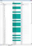
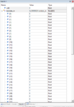
For this thread, I managed to generate sampling rate in 1MSPS with Hardware NSS output in SPI DMA mode. However, I couldn't read the variables of 'volt' and 'testdata_in' during debug session. I also tried with 500kHz sampling rate but the results are the same. So how can I solve the problem? I want to monitor the conversion values during debug session.

My code in main.c file and in int main() structure:

Code:
/* USER CODE BEGIN 2 */
	
	spidata[0]=0x00;       // Set everything up  before you start the exchange
	spidata[1]=0x00;
	HAL_SPI_TransmitReceive_DMA(&hspi4,spidata,ADC_Buf,2);
	Sample = (((uint16_t) ADC_Buf[1]) << 8 | ADC_Buf[0]) & 0x0FFF; 
	volt = (float)(Sample * (3.3 / 4096.0)); //
	testdata_in[i++]=volt;
	i %= 60;

  /* USER CODE END 2 */

  /* Infinite loop */
  /* USER CODE BEGIN WHILE */
  while (1)

The debug session results:
adc_debug.PNG
 

Hi,

Please read about the limitations in debug mode.
I doubt it can process a datarate of 1Msample/s. Not even close to that rate.

And I doubt your eyes can follow such a datastream.

Obviously you need to store the incoming data in SRAM ... and process them later.

You also should get a clue how long a floating point multiplication plus division takes.

Klaus
 

Thank you!

I place a delay and call back function in the code.

Now I read some values, but the SPI DMA stops the GPIO SET and RESET control in a timer ISR. Maybe I discuss it in a new thread.
 

Hi,

The SPI_DMA does not stop anything.
Usually it raises an interrupt .... and maybe you have anything blocking in this ISR.

Klaus
 

Status
Not open for further replies.

Similar threads

Part and Inventory Search

Welcome to EDABoard.com

Sponsor

Back
Top