Continue to Site

Welcome to EDAboard.com

Welcome to our site! EDAboard.com is an international Electronics Discussion Forum focused on EDA software, circuits, schematics, books, theory, papers, asic, pld, 8051, DSP, Network, RF, Analog Design, PCB, Service Manuals... and a whole lot more! To participate you need to register. Registration is free. Click here to register now.

reverse phasing protection for mosfets in inverter circuits.

Status
Not open for further replies.

spiba

Junior Member level 2
Joined
Feb 1, 2010
Messages
23
Helped
1
Reputation
2
Reaction score
1
Trophy points
1,283
Location
india
Activity points
1,477
Normally in inverter circuits mosfets fail when another phase is connected accidently by electricians
to the output of an inverter .This leads to all mosfets connected in parrelal in both half bridge to Blow. Normal overload protection circuit of the inverter don't work under these conditions. Some manufacturers claim as their inverters design being Reverse phase protected .How to sense the different phase at the transformer output ( 230 Volts tap at output going to lighting load) and protect the mosfets ?
 

One "trick" that I have seen have been to connect an inductor inbetween the MOSFET-switches. The cause is for the current to rise not too quickly and giving the supervising electronics some time to react. Generally speaking, power MOSFETs can withstand over-current better than one can believe, but over-voltage is an instant killer. Play with some ideas of incorporating one or a few inductors in the schematics and calculate what-if so you can minimize the risk of blowing any MOSFETs. Sensing the different phases could be achieved in several ways, I am sure, but the big deal is to avoid destucting any components.

/Pim
 

Your description is unclear. "Reverse phase" isn't the same thing as "output phase short" in my opinion.
I also don't understand which actual circuit this sentence is referring to:
How to sense the different phase at the transformer output ( 230 Volts tap at output going to lighting load)
 

Hi spiba,
Normally in inverter circuits mosfets fail when another phase is connected accidently by electricians
to the output of an inverter
It is unclear as FvM said, do you mean while the inverter is working and the AC LINE is connected to the output of the inverter output side?
Please elaborate.
 

One "trick" that I have seen have been to connect an inductor inbetween the MOSFET-switches.
How do you suggest ? and what value? My inverter is using center tap Transformer with 24V dc and two plates of IRFP 250 Mosfets ( Three Parralal) in each plate) . Usualy all blow when inverter is running and there is a reverse phase on secondary ( 230 VAC) of transformer.
"Generally speaking, power MOSFETs can withstand over-current better than one can believe, but over-voltage is an instant killer."
I fully agree with you that 90 % of the mosfets are damaged due to Overvoltage rather than overcurrent . So i am looking for the best possible protection techniques for this.
"MOSFETs. Sensing the different phases could be achieved in several ways, I am sure, but the big deal is to avoid destucting any components."
How ? Instantly without any damage being caused?
 

An inverter with transformer output has sufficient leak inductance to limit the short circuit current to a value, that can be handled by the output transistors at least for several 100 us. The output stage needs overcurrent sense and shutdown.
 

But as i and Pim said earlier that mosfets are killed by over voltage immideatly .Since reverse phasing from a different phase( where threre are3 phase present in house wiring although the inverter is single phase) may cause havoc so overcurrent sense at output ONLY will not work according to what
i feel.
 

Unfortunately, you didn't manage to clarify that you are talking about 400V connected to the transformer output. I have been asking before about the meaning of the vague "reverse phasing" term.

Overvoltage shouldn't be still the primary problem, howver. IRF250 has a voltage rating of 200 V and also some avalanche clamping capabilty for overvoltages above this limit. Even if you manage to connect 400 V instead of 230 to the output transformer, the drain voltage won't go above e.g. 100 V.

A serious problem arises however from the fact, that the bulk diodes are forward biased, sourcing high reverse current to the battery.
 

Hi,
Normally in inverter circuits mosfets fail when another phase is connected accidently by electricians
to the output of an inverter

Absolutely confusing. Not clear at all what you mean by this and what is your problem.
And this is making more complicated the subject.
But as i and Pim said earlier that mosfets are killed by over voltage immideatly .Since reverse phasing from a different phase( where threre are3 phase present in house wiring although the inverter is single phase) may cause havoc so overcurrent sense at output ONLY will not work according to what
i feel.
 

Right FVM that IRFP250 are rated at 200V and i have overload protection by sensing the drop on a shunt across battery negative and inverter immidietly trips with 150 % excess load. But But in case of 400v at output of transformer all mosfets
simply blast. In normal conditions mosfets are not harmed for years .

---------- Post added at 06:24 ---------- Previous post was at 06:23 ----------

Right FVM that IRFP250 are rated at 200V and i have overload protection by sensing the drop on a shunt across battery negative and inverter immidietly trips with 150 % excess load. But But in case of 400v at output of transformer all mosfets
simply blast. In normal conditions mosfets are not harmed for years .
 

You should analyze more thoroughly what happens in the circuit. Did you undertstand the bulk diode conduction problem? It can't be handled by a inverter shut-down, you have to disconnect the battery, respectively allow the transformer center tap to rise to about 40V.

P.S.:
Absolutely confusing. Not clear at all what you mean by this and what is your problem.
Confusing yes, but understandable though. The problem is about reverse feeding the output of a 24V to 230V inverter accidentally with 400 V AC.
 

No i don't understand what you mean by bulk diode conduction problem ? can you explain in more details ? further i also did not understand " to allow the center tap of transformer to rise to 40V"
 

The bulk diode is usually shown in the MOSFET schematic symbol. e.g. of IRF250. It starts to conduct, when the peak voltage between transformer and MOSFET drain exceeds the battery voltage by 0.7 V.

Assuming a square wave inverter transformer design (windings ratio 24:230 + 10% = 1:10.5), and 400 V AC connected to the secondary, you get about 40 Vrms / 55 Vpeak at the primary.
 

I think he means that if the electrician while working accidentally connect the Neutral to an other Phase. So there will be 440 V AC (Dual Phase Voltage) and naturally will burn all the DEVICES in the out put circuit while the inverter is in the charging phase.
 

One "trick" that I have seen have been to connect an inductor inbetween the MOSFET-switches.
How do you suggest ? and what value? My inverter is using center tap Transformer with 24V dc and two plates of IRFP 250 Mosfets ( Three Parralal) in each plate) . Usualy all blow when inverter is running and there is a reverse phase on secondary ( 230 VAC) of transformer.
"Generally speaking, power MOSFETs can withstand over-current better than one can believe, but over-voltage is an instant killer."
I fully agree with you that 90 % of the mosfets are damaged due to Overvoltage rather than overcurrent . So i am looking for the best possible protection techniques for this.
"MOSFETs. Sensing the different phases could be achieved in several ways, I am sure, but the big deal is to avoid destucting any components."
How ? Instantly without any damage being caused?

Not knowing your exact schematics but having read the other replies to this thread maybe I can give a few additional hints: If using a transformer and somehow get the MOSFET-switches combined with whatever may be feeded to the other end (secondary?) of the transformer which has a leakage inductance (all real-world transformers have that), then the current in your transformer in case of this failure mode will rise very quickly. The core of the transformer will be magnetically saturated. Let's say that you at this point cut off the MOSFET:s, then the magnetic energy from the transformer most have somewhere to go. It goes into the circuit which has the highest resistance, which will be your now turned-off MOSFET:s. Compare it with a regular ignition coil used for cars, same principle. To be able to analyze your schematic and application including the failure mode you describe requires much more info than is given in this thread. However, now the hints: You can use Transils (overvoltage transient diodes) connected across the MOSFET:s. source and drain. Transils are very fast and can limit the voltage spike from the released magnetic energy from your transformer. Another way to achieve this is to connect zenediodes from drain to gate (and see what-if the MOSFET get its driving from anouther source and the gate voltage instead will be driven upwards by force due to these zenerdiodes). The intention here is that when the drain voltage of the MOSFET vill rise dangerously high, then these zenerdiodes start to conduct and will make the MOSFET in question to partly start to conduct. In so doing it will pass current from drain to source of the MOSFET and this leads to the high-voltage spike over the MOSFET:s drain-source to be limited. If there is enough power behind that high-voltage spike then as the zenerdiodes conducts, the gate voltage of the MOSFET will rise more and the MOSFET will just conduct more current and in so doing decrease the high-voltage spike over drain-source even more efficiantly. These small hints can find value if there really are short duration high-voltage impulses which blows the MOSFET:s. My suggestion of incorporating inductors (maybe in very rough intervall ~100uH...1mH or something similar) will (if connected in the right way) result in that when something goes wrong then the current through the MOSFET:s just rises slower and may give your over-current section of the design time to actually react and cut the driving voltage to your MOSFET:s. Don't forget that as there is a quite considerable capacitance between the gate and source of a MOSFET and this phenomenon requires your circuit which very quickly must bring the gate voltage down to also be able to provide quite some current. It may be in the order of one or several Ampere for the MOSFET to react quick enough. Also, there is a capacitance between the drain and gate. If the drain voltage rapidly rise as a result of the gate voltage rapidly go down, then you have still some current flowing internally via the built-in drain-gate capacitance which tries to counteract a decrease of the gate voltage. But anyhow, if having in the order of 230-400 Volt to play with and running a potential of having this level of voltage (with an enough current capacity behind)...then you better think out a defence design for the MOSFET:s very carefully. Otherwise it is very possible to end out with a blueish flash and a bang. As noted, a schematic would help, and a clear explanation of what you seen gone wrong and due to what reason. It would thus be possible to simulate the circuits. Another small hint: There exist something called "smart MOSFET:s" which were made by Infineon and Philips (maybe more manufacturers exist than these). Infineon's smartness was in that they had glued a tiny temperature dependent resistor directly to the chip itself. Of course they had quite some other components integrated at the same chip to make it "fail-safe". It worked very well. The version I used in a design is called BTS650 (if I remember correctly). It could withstand a very high shortcircuit current indeed without being damaged. It just shut itself down for a fraction of a second and after that then again fully operable. Philips versions are based on integrating a diode on the same chip as the power MOSFET and it is then this integrated diode which senses the chip-temperature and shut of the smart MOSFET switch. I don't know though if any suitable smart MOSFET:s exists for your purpose having in mind what voltage/current/dissipation power/switching speed your design requires. But please have a look at these smart MOSFET:s and maybe you have a solution which works for you.

/Pim
 
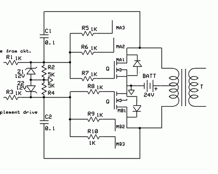
i am attaching my schematic it is drive 50htz drive for square wave inverter (a Pdf file)
 

Attachments

  • inverter drive.pdf
    10.2 KB · Views: 237
i am attaching my schematic it is drive 50htz drive for square wave inverter
Is the inverter used for charging the battery? You discussed the problem of connecting 400 VAC to the transformer output, but what happens, if you connect "only" 230 V?

As Raza mentioned in post #14, inverter reverse operation for battery charge is a ususal method. I guess, it should work with this circuit, but current limiting is only achieved by transformer parameters leak inductance and windings resistance. However, with 400 VAC at the output, you get 55 V instead of 30 Vpeak driven to the battery. Besides a risk of damaging the battery, the current will exceed the MOSFET bulk diode ratings and "blow" the transistors.

Before this reverse voltage problem isn't handled, you don't need to think about switching overcurrents and overvoltage protection.
 

The downloaded PDF could not be opened with me.
 

5_1316015811.gif

The conduction through internal diodes will not stop even if you cut drive to gates. Internal diode bursts due to overcurrent passing through them .This is what FvM is talking about.
 
Last edited:

please note that my charger is completely separate . i am using a separate SMPS charger card charging the batteries and i dont need mosfet diodes for charging.

The conduction through internal diodes will not stop even if you cut drive to gates.
Does this mean i should use mosfets without internal diodes instead of IRFP 250 ? Will this solve my problem ?
When you have few inverters installed all is well .But when you have hundreds of them in different places such problems become evident . So i have to find a solution to reduce
the failure percentage.
 

Status
Not open for further replies.

Similar threads

Part and Inventory Search

Welcome to EDABoard.com

Sponsor

Back
Top