mtwieg
Advanced Member level 6

Hello,
First of all, I can't state the application in detail (it's ongoing research), but I think I can describe the system in enough detail. I'm asking this on behalf of a friend who has been fighting this issue for a while. Neither of us are experts on PLLs or phase noise, so we're looking for advice.
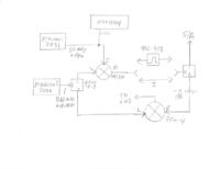
Basically we're trying to upconvert (to around 950MHz) a narrowband (about 50MHz, BW is about 500KHz) signal and transmit it wirelessly (SSB) to a receiver, which downconverts it back to the original 50MHz signal with as little error as possible. To generate the carriers on the receiver and transmitter sides he is using a combination of a ADF4111 PLL and a MAX2623 VCO. A 5MHz reference is connected to both sides via a coax cable. A block diagram is shown below.

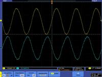
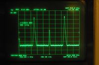
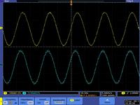
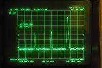
Everything looks fine on the bench (as shown by our spectrum analyzer). We can see the signal reproduced accurately over the whole system. However, when we use it to transmit actual data, we are sometimes observing artifacts that seem to be due to low frequency phase drift/error in the downconverted signal. After messing around with the system a lot, he found that these artifacts only appear when the PLLs are set such that the output of the VCO is not an integer multiple of the 5MHz reference (produced by a 10MHz oscillator with its output divided by a flip flop). The PLL has an internal reference divider (R counter) so that frequency resolution can be smaller than that of the 5MHz reference, which he desires. At first he was dividing it down to 200KHz internally (R=25), then multiplied it by N=~4750 to get around 950MHz. He would get noise results unless the the carrier was a multiple of 5MHz (N was a multiple of 25).
Even stranger, we tried a 10MHz reference in as well, and we saw the same thing. Like if we use a 5MHz with R=1 and N=181 to get 905MHz, it will give good outputs. But if we use 10MHz with R=2 and N=181 to get 905MHz, we will get noisy output. But then if we use fr=10MHz, R=2, N=180 to get 900MHz, it will work well again. This is really perplexing, since internally the divided reference should be exactly the same signal in all of these cases. But somehow these different settings get different results.
Has anyone ever encountered an issue like this? We've tested this exhaustively, and the problem is very consistent. The frustrating part is we can only observe this when doing a real experiment and reconstructing real data. When looking at noise on the signal analyzer, everything looks the same, despite getting different results from the experiment. Maybe we're not using the signal analyzer correctly...?
Thanks,
-Mike
First of all, I can't state the application in detail (it's ongoing research), but I think I can describe the system in enough detail. I'm asking this on behalf of a friend who has been fighting this issue for a while. Neither of us are experts on PLLs or phase noise, so we're looking for advice.
Basically we're trying to upconvert (to around 950MHz) a narrowband (about 50MHz, BW is about 500KHz) signal and transmit it wirelessly (SSB) to a receiver, which downconverts it back to the original 50MHz signal with as little error as possible. To generate the carriers on the receiver and transmitter sides he is using a combination of a ADF4111 PLL and a MAX2623 VCO. A 5MHz reference is connected to both sides via a coax cable. A block diagram is shown below.
Everything looks fine on the bench (as shown by our spectrum analyzer). We can see the signal reproduced accurately over the whole system. However, when we use it to transmit actual data, we are sometimes observing artifacts that seem to be due to low frequency phase drift/error in the downconverted signal. After messing around with the system a lot, he found that these artifacts only appear when the PLLs are set such that the output of the VCO is not an integer multiple of the 5MHz reference (produced by a 10MHz oscillator with its output divided by a flip flop). The PLL has an internal reference divider (R counter) so that frequency resolution can be smaller than that of the 5MHz reference, which he desires. At first he was dividing it down to 200KHz internally (R=25), then multiplied it by N=~4750 to get around 950MHz. He would get noise results unless the the carrier was a multiple of 5MHz (N was a multiple of 25).
Even stranger, we tried a 10MHz reference in as well, and we saw the same thing. Like if we use a 5MHz with R=1 and N=181 to get 905MHz, it will give good outputs. But if we use 10MHz with R=2 and N=181 to get 905MHz, we will get noisy output. But then if we use fr=10MHz, R=2, N=180 to get 900MHz, it will work well again. This is really perplexing, since internally the divided reference should be exactly the same signal in all of these cases. But somehow these different settings get different results.
Has anyone ever encountered an issue like this? We've tested this exhaustively, and the problem is very consistent. The frustrating part is we can only observe this when doing a real experiment and reconstructing real data. When looking at noise on the signal analyzer, everything looks the same, despite getting different results from the experiment. Maybe we're not using the signal analyzer correctly...?
Thanks,
-Mike


