Continue to Site

Welcome to EDAboard.com

Welcome to our site! EDAboard.com is an international Electronics Discussion Forum focused on EDA software, circuits, schematics, books, theory, papers, asic, pld, 8051, DSP, Network, RF, Analog Design, PCB, Service Manuals... and a whole lot more! To participate you need to register. Registration is free. Click here to register now.

Designing an Opamp for 4 GHz

Status
Not open for further replies.

naalald

Full Member level 4
Full Member level 4
Joined
Dec 2, 2006
Messages
216
Helped
30
Reputation
54
Reaction score
5
Trophy points
1,298
Activity points
2,627
Designing an Opamp with 4 GHz BW

I'm designing an opamp and need 78 dB gain and 4 GHz BW with 3.5 pF Cload and 2.5 V supply voltage. I can get the gain with a single stage folded-cascode opamp, but the best result for the BW is just 1.8 GHz. Would you please let me know your opinion about this design and any suggestions for the structure?
I'm using BiCMOS process.
Thank you.
 

The gain of op-amp is gm*Rout. As you say the 1/(2*pi*CL*Rout) is 1.8GHz. Therefore, It is possible to find that Rout is ~25 ohms! As your gain is 7900, the value of gm is 7900/25=316 mho which is very huge. I am interested at how much current, you are dissipating. The unity gain bandwidth of this opamp that you need is 31.6 THz !!! which is very big. Therefore at first do a sanity check and find the ft of the transistors.

Your requirement is really tough ( High Gain+ High BW). The best way to design ( if it's possible), using multiple stages with tapering.

---------- Post added at 02:57 ---------- Previous post was at 02:40 ----------

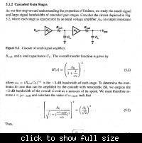
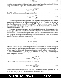
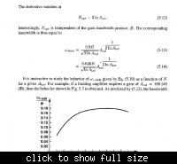
And here is some tips about Optimum number of stages for identical stages for specified value of gain if fT is given.


it looks like eq 5.14 could be simplified quite a bit...
 

Status
Not open for further replies.

Part and Inventory Search

Welcome to EDABoard.com

Sponsor

Back
Top