yahootew3000
Junior Member level 3

cpu design verilog
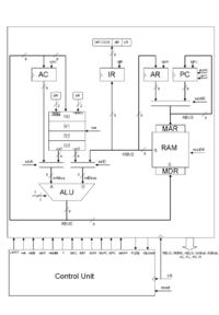
Introduction To The Design of CPU using RTL Approach.
This CPU is a simple 8-bit processor with 8-bit address bus. The architecture is based on accumulator-based design. The instruction set is grouped into few categories which is shown as below:
1. Data manipulation
a. ADD X Add the value in memory to the accumulator.
b. SUB X Subtract the value in memory to the accumulator.
c. XOR X Exclusive-OR logic operation value in memory to the accumulator.
d. AND X Perform AND logic operation value in memory to the accumulator.
e. ADR Add between registers.
2. Data transfer
a. MVI Move the immediate data to the specified register.
b. MVD Move the specified memory data to the specified register.
c. MOV Move data between registers.
d. LDA X Load the memory data to the accumulator.
e. STA X Load the accumulator to the memory data.
3. Program control
a. BRN X Branch if the value in the accumulator is negative.
b. JMP X Jump to a specified address.
6. Shifting
a. SHR Shift one bit of the register to the right.
b. SHL Shift one bit of the register to the left.
5. Miscellaneous
a. HALT Stay no operation.
b. NOP No operation until next instruction.
The design is using the Λltera Quαrtus II 7.2


