anotherbrick
Full Member level 4

- Joined
- Jan 10, 2009
- Messages
- 222
- Helped
- 1
- Reputation
- 2
- Reaction score
- 1
- Trophy points
- 1,298
- Location
- Istanbul , Turkey
- Activity points
- 3,190
hi dear forum members
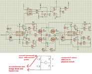
my question in the picture
thank you

my question in the picture
thank you