Continue to Site

Welcome to EDAboard.com

Welcome to our site! EDAboard.com is an international Electronics Discussion Forum focused on EDA software, circuits, schematics, books, theory, papers, asic, pld, 8051, DSP, Network, RF, Analog Design, PCB, Service Manuals... and a whole lot more! To participate you need to register. Registration is free. Click here to register now.

SEPIC dc dc converter power supply 24W [12V@2A]

Status
Not open for further replies.

seridj_mse

Member level 2
Member level 2
Joined
Jan 18, 2021
Messages
53
Helped
0
Reputation
0
Reaction score
2
Trophy points
8
Visit site
Activity points
311
dear experts ,


After a hard #work 😮‍💨to reduce noise for certify our equipment directive CISPR 16-2-3 class B with LNE , i had basically tow problem :


1- harmonics 50 MHz oscillator for Ethernet 10/100M design in mother boar. that is not the point of this post.


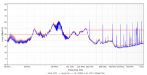
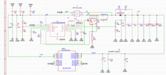
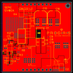
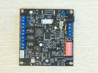
2- noise in power supply of our mother board we use a SEPIC DC DC converter 24w large input 9-30v and fixe output 12v@2A. for conducted emissions it was good 👍 but for radiation emissions it was very Noisy 👎 so I started dig into the issue and what is the source of this noise, hot loop as small as possible🙃, ground MOSFET as close as possible to gnd output capacitor🙃, change référence of components with better intrinsic characteristics 🙃change PCB placement and layers 🙃.... keeping in the mind 🤔 the price of those changes 🤑and the most important thing the right functioning of the board 🤷🏿‍♂️


So now i can say i was very successful reduce noise 😎 but when i measured temperature of components, the surprise🤬 :


-Before modification at max load 2A :


- Coupled inductor : 49°

- Diode : 55°

-Mofet : 45°


After modification :


- Coupled inductor : 64° 🔥

- Diode : 68° 🔥

- Mosfet :77° 🔥🔥


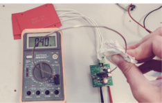
Note : i take those measurements with my old multimeter and K probe thermometer 🌡️

So maybe i know why 🧐 i use a 50R for gate Mosfet so i think 💬 i should find another method like use 4 layers 🙃 PCB.


TO YOUR KEYBOARD for any help 🤠
 

Attachments

  • 2.jpg
    2.jpg
    212.7 KB · Views: 209
  • Captdddddure.PNG
    Captdddddure.PNG
    683.3 KB · Views: 206
  • IMG_20221118_162958.jpg
    IMG_20221118_162958.jpg
    3.2 MB · Views: 205
  • 1.PNG
    1.PNG
    177.3 KB · Views: 223
  • 1re.PNG
    1re.PNG
    77.9 KB · Views: 238
  • 1v3PNG.PNG
    1v3PNG.PNG
    122.8 KB · Views: 252
Last edited:

Hi
I will not use SEPIC for high power > 10W, as its ripple current too high and low efficiency.
The most advantage of SEPIC is safety when have trouble will controller, Input will not connect directly to Ouput.
I suggest you change to BUCK & BOOST (not BUCK-BOOST topology, as my tested real design, its is very cool for 12V3A, and will range input & output. Faster adapt for control loop and load respond.
Depend of output, it will operate in BUCK or BOOST mode.
The hot on Coupled inductor is not too stress, because it is copper & ferrite, can accept higher temperature.
For Diode & Mosfet, you have to optimize selection/type.
Diode should have low VF, capacitor.
Mosfet should transist faster, low input capacitor, low turn on ringing - reduce EMI, balance between switching & conducted lost.
1669093560912.png
 

Attachments

  • ups 12v camera board.jpg
    ups 12v camera board.jpg
    263.6 KB · Views: 212
Hi,

Thanks for ur replay and those informations , so ur solution is good but that take time for us to adapt it bcs we need time ( (research and development, validation test ...).

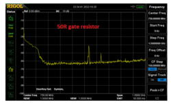
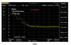
And for our SEPIC efficiency now is good , so i need only to reduce noise for certification and i can say the gate resistor gate mosfet help me reduce noise but raise the temperature so without this resistor i can mesure good temperature :

- Coupled inductor : 50°
- Diode : 56°
- Mosfet :50°


But it does not pass certification .
 

Attachments

  • 50R.PNG
    50R.PNG
    62.6 KB · Views: 184
  • 0R gate.PNG
    0R gate.PNG
    107.6 KB · Views: 174

Hi
With low voltage as 9-30V, the dv/dt is quite low. So, when you failed with 0R/10R Rg, it maybe problem with Mosfet optimize and set point of operation.
Manufacturers as Infineon (IFX), NXP, Onsemi, Nexperia, Alpha Omega, Ti, ... had optimize many Mosfet to fit many design application. But, they never show how to use them correctly. Because, condition is effected by many thing arround. Not only by Mosfet. Our responsitivity of designer is find out which is th best fit.
Mosfet turn on too fast, cause high spike turn on current (dirty current), it appear because Mosfet has its Cds and C_parallel of inductor, and capacitor of your trace/pad:
1669225526559.png

So, you should oftimize turn on/off or rising & failling time for mosfet. First, try to charge to gate mosfet by 50R, and quick discharge by another way faster as diode serial with small resistor R + D = 10R + 1N4148. This will help reduce more switching lost.
As you said, all power of your components Mosfet, diode, inductor is hot. That mean maybe lost of frequency/switching + conducted lost mad heat. You are setting controller ~300kHz, it is not so high. Inductor core type is Ferrite, it will well work this frequency. -> But the inductance too low, just 10uH for 12V x 2A = 24W. This make high input ripple current -> more noisy. -> Try to increase switching frequency, reduce Rg, measure too see. -> Try to increase inductance also.
Try to use correct right capacitor type for application, if not, it does not meaning. Electrolyse capacitor need cover the Ipp @ base switching frequency, Ceramic hase low impedance @ xx base switching frequency. Capacitor is not only capacitance & voltage.
 
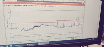
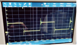
thanks wery well, ur answer is very clear and enriching i will see what i can do . butmy problem i dont have speed scope with large BW. But when i pass test certification i used scope 1Ghz and save screen :

normal voltage is 25V and pic without snuber /Rg is up to 40V so 15V overvoltage and with snuber 35V . in this time i use RC snuber to reduce noise 10R+220pF i say with this low value of capacitor the the resistor heats up so i should use 2512 pakage for 2 or 3W ....
 

Attachments

  • 1669282372786.png
    1669282372786.png
    1.1 MB · Views: 180
Last edited:

Hi
Your spike voltage cause from layout.
I just rebuild your design in LTspice - simulation as below, with same condition (300kHz, 10uH:10uH). I just add very small leak inductor on Trace & Mosfet, spike voltage will appear and peak to 40V. The Ipp = ~4.5A.
The FFT show that circuit has resonant point near 50Mhz.
Your test result show that you have trouble with harmonic frequency of 50MHz: 150 - 250 - 350 - 450 - 500 - 550 Mhz - f_3x - f_5x - f_7x - f_11x
When trace on PCB were excited by pulse, it will ringing with it resonant frequency. So we need layout carefully to reduce/ absorb these ringing. R-C snubber used to reduce dv/dt, that will help reduce harmonic excited other trace. But, it is not adapt to all case.
You pour polygon all PCB surface, that mean, you don't care or control current loop. We will not sure how current flow, where current run. Pour all PCB is not for professional designer.
If current charge and discharge in same way, have trouble. It will radiate double noise to environment.
Confirm that: dc current run through the shortest resistance path, but ac current through the shortest impedance path. This means dc & ac current in poured PCB is not same path. TROUBLE !!!!
Do you know microven-oven principle ?
You poured double PCB made a C, the far connection vias connect two GND mad L. When excitation signal appear, the L&C will ringing with very high frequency. That why, PCB layout has rule: place vias near cornner of PCB, or beside the high speed path. The space ~= 1/10 length of that frequency. You didn't do this on PCB.
Don't use vias too much in switching power current path, it is not as imagine, it has high impedance, made high ripple, high leak inductance (90 degree cornner current way). Try to place all power trace, current loop in same layer.
I recommend you redesign PCB. Don't pour when you are not sure its purpose. Don't pour plane with 90 degree conner. This will strongly radiate noisy.

1669486007160.png

1669486040335.png

1669487831748.png

1669486538947.png
 
dear experts ,


After a hard #work 😮‍💨to reduce noise for certify our equipment directive CISPR 16-2-3 class B with LNE , i had basically tow problem :


1- harmonics 50 MHz oscillator for Ethernet 10/100M design in mother boar. that is not the point of this post.


2- noise in power supply of our mother board we use a SEPIC DC DC converter 24w large input 9-30v and fixe output 12v@2A. for conducted emissions it was good 👍 but for radiation emissions it was very Noisy 👎 so I started dig into the issue and what is the source of this noise, hot loop as small as possible🙃, ground MOSFET as close as possible to gnd output capacitor🙃, change référence of components with better intrinsic characteristics 🙃change PCB placement and layers 🙃.... keeping in the mind 🤔 the price of those changes 🤑and the most important thing the right functioning of the board 🤷🏿‍♂️


So now i can say i was very successful reduce noise 😎 but when i measured temperature of components, the surprise🤬 :


-Before modification at max load 2A :


- Coupled inductor : 49°

- Diode : 55°

-Mofet : 45°


After modification :


- Coupled inductor : 64° 🔥

- Diode : 68° 🔥

- Mosfet :77° 🔥🔥


Note : i take those measurements with my old multimeter and K probe thermometer 🌡️

So maybe i know why 🧐 i use a 50R for gate Mosfet so i think 💬 i should find another method like use 4 layers 🙃 PCB.


TO YOUR KEYBOARD for any help 🤠

I still suspect you may have conducted issues emissions issues and depending on the loop area of your wiring your problem will vary. By adding all the damping you've just added loads of loss hence the heat. Theres a few things i'd look at if i were you

1. Add an input filter as the switching currents will be in the power lines, the size of the loop of the power wires will make them antenna, if you can't add a filter then make them a twisted pair or ensure the are in close proximity (touching) and hope for the best. Bigger the loop the worst it will be for radiated emissions. You haven't shared the details for the input current ripple of your design but you only need uA's of switching ripple to give you all those harmonics.

2. Similar to the input. Your output inductor is far too physically small and is likely not an inductor at all with a output current of 2A as its saturated, The Datasheet suggest its max Current is 1.2A but for it to be 1uH the current is more like 200mA. You need to replace it with a propper power inductor (which is screened) with at least a 2.5A rating. Currently its doing next to nothing for you. You have 2 loads connected and as the wires aren't twisted you have two loop areas to radiate unless you remove the secondary switching currents off the line.

You only need mA of switching ripple in wire loops to create quite strong radiated emissions.
 
Last edited:

Trying to model the emc is a complete waste of time as the real world results will be very different due to parasitic damping effects and different gate drive ...
 

Hi, thanks for your reply and information.

You pour polygon all PCB surface, that mean, you don't care or control current loop. We will not sure how current flow, where current run. Pour all PCB is not for professional designer.
i dont know how i can do professional pcb and control current return path (if iam an professional designer pcb i dont think i post this TOPIC). I tried with one version to delete gnd plane in top layer and use only piste and via gnd but (2layer and 4 layer it was my first change) i didnt see a big diffrence so i dont know how i can do better, that why i ask help in forum ?

1669816724468.png

Confirm that: dc current run through the shortest resistance path, but ac current through the shortest impedance path. This means dc & ac current in poured PCB is not same path. TROUBLE !!!!
how i can know if they have same path or not ?


Do you know microven-oven principle ?
no.

You poured double PCB made a C, the far connection vias connect two GND mad L. When excitation signal appear, the L&C will ringing with very high frequency. That why, PCB layout has rule: place vias near cornner of PCB, or beside the high speed path. The space ~= 1/10 length of that frequency. You didn't do this on PCB.
oky, if u mean switch frequency its around 333khz so Wavelength is 900m so 90 m ?
Try to place all power trace, current loop in same layer.
i think that what i did , i have only 2 piste on the bottom , all other piste are in TOP
1669817334535.png


--- Updated ---

I still suspect you may have conducted issues emissions issues and depending on the loop area of your wiring your problem will vary.
i didnt do test with this version , but with the origial pcb version it was good. but i will do with my final version to see if i didnt worstit.

By adding all the damping you've just added loads of loss hence the heat. Theres a few things i'd look at if i were you
yes but when u say "all the damping" if talk about R9,C17 (DIODE) and R10, C18 are not connected (NC) , for me i have only gate resistor 50R.

1. Add an input filter as the switching currents will be in the power lines, the size of the loop of the power wires will make them antenna, if you can't add a filter then make them a twisted pair or ensure the are in close proximity (touching) and hope for the best. Bigger the loop the worst it will be for radiated emissions. You haven't shared the details for the input current ripple of your design but you only need uA's of switching ripple to give you all those harmonics.
1-about input filter i have in mother borad PI filter but i use only inductor 150uH
https://www.mouser.fr/datasheet/2/445/7447480151-1722442.pdf
2-for the input cable and output too , i do the test with probe near filed and RIGOL analyzer and dont have any noise on the cable !!

i have
2. Similar to the input. Your output inductor is far too physically small and is likely not an inductor at all with a output current of 2A as its saturated, The Datasheet suggest its max Current is 1.2A but for it to be 1uH the current is more like 200mA. You need to replace it with a propper power inductor (which is screened) with at least a 2.5A rating. Currently its doing next to nothing for you. You have 2 loads connected and as the wires aren't twisted you have two loop areas to radiate unless you remove the secondary switching currents off the line.
oky i will see but

Current - Saturation for my inductor i see in Altium 2.1A Current Saturation and 2.3A Current Rating !!


Last edited:

Hi
i didnt see a big diffrence
We talked much about the in your previous thread.
Sadly you ignored all this in your actual PCB layout (At least it seems so)

Taihung is very right with all he is writing.

****
You didn´t see a lot differrence, because:
* you were focussed on the near field of the diode. You can´t change physics. You can´t have signal and it´s return path at exactly the same location. Thus you always have near field, that´s unavoidable. But with a good layout it almost cancels out in a distance of 10mm or 30mm. A bad layout will never cancel out that good. A bad layout causes
* you did not use standardized eqippment and measurement methods.
* you did not give feedback on what we requested: Like far field measurements.
* Also you will see a big difference in HF (differential mode) on the input and output. (if you look at it)
* ... and the conducted RF (if you look at it)

Klaus
 

Hi
Yes, you improved layout abit. From your side it maybe not clear all "trick" to do with design.
I really don't like using vias in power application and "auto stiching vias feature"
Your current paths is still not perfect yet.
You did not separate power GND vs signal GND. The GND can complete on TOP, why need through vias to bottom ?
Input filter or ouput filter maybe not help you so much, sometime made more noise to circuit. When it reduce high frequency, it can ringing higher amplitude low frequency. CLC filter will not filt high frequency as Mhz as you expect. It should be use air core indutor + film/ ceramic capacito with low value. Not like your design 10uF & 150uH. As my design power module BUCK: input & output ripple thus 3mVpp @ full load 5V 3A.
If you don't mind, share project schematic & pcb to me, without company info, no logo. I will help you correct the rest in few days. Only hope you can share test result to forum.
1669824566631.png

1669825758215.png
 
Sadly you ignored all this in your actual PCB layout (At least it seems so)
No i didnt , but as i said i am not professional pcb design yet, so maybe i understand but i dont know how i can apply it my pcb design .....
Taihung is very right with all he is writing.

maybe, but what i can say about #4 :

1- it is useless to increase the switching frequency it is also risky. The noise spectrum will be higher at high frequency. As you can notice you are fighting with high frequency and you see how it is difficult for unshielded board.

2- If we increase our inductance to decrease the current ripple we will pay it buy heating in the core and copper because we will need more turn or/and change ferrite material and dimension. Core loss + copper loss.

3- it is not suitable to use high frequency when it is not required by the volume "I mean we don't need to decrease the volume of converter for our application". The cost of controller and components will increase, the circuit becomes sensitive to the noise and may not compensate it ...etc It is suitable to use low frequency as it is easy to filter simply.


Your other thread had 60+ posts.
This is way over what a forum thread is meant to be.

A forum can not replace school or your own learning, like going through tutorials, papers, videos.
Also you can´t expect that others do your job. (again and again)

If you can´t repeat what you´ve done in your other thread ... I don´t know what to do.
I won´t spent the time to repeat the same as in the other thread.

Maybe consider to hire a senior designer to assist you.

Klaus
 

Hi
From your side it maybe not clear all "trick" to do with design.
yes its not clear yet !

I really don't like using vias in power application and "auto stiching vias feature"
ok i can understand.

Your current paths is still not perfect yet.
yes but as i share the result its oky with 50R so i want use only 5R and try to reduice nois noise with other method as i said 4 layer or change current path but the pcb design its now verry better then the first one but i should test the contucted emission if its still oky ........
You did not separate power GND vs signal GND. The GND can complete on TOP,
i dont know how i can do it and i should be sure it will be decrease my noise to do it ....

why need through vias to bottom ?
i use or i want use only 2 layer pcb so plane GND is in the bottom for me.But i want learn if its possible design without GND in the bottom and i will be verry happy
Input filter or ouput filter maybe not help you so much, sometime made more noise to circuit.
yes by test i change and i test a lot of value but no changing in radited noise but in conducted they are useful
If you don't mind, share project schematic & pcb to me, without company info, no logo. I will help you correct the rest in few days. Only hope you can share test result to forum.
oky i can and i sharte it schematic what i cant share is the vlaue of PI regulator R7,C12,C13 and i want learn and do all change by myself , in this case i can ask an comapnay to do the job for me.


A forum can not replace school or your own learning, like going through tutorials, papers, videos.
Also you can´t expect that others do your job. (again and again)
You can see my reply #14 , and if u think i have school lever its not a probelem for me. reply me about post #12 u said Taihung is very right with all he is writing. and me i said tank you Taihung for all ur response but iam not agree with u in this point and i say why. This a method to change idea and lean
I won´t spent the time to repeat the same as in the other thread.
i never ask u to reply and spent time , if i post my question is about to change informations and learn each other
Maybe consider to hire a senior designer to assist you.
No i will be a senior in some years and i dont want the easy method i am here to learn , if do something wrong or this forum doest like what i do i can change it and never post my question here , no problem
I can add its important design to cost , iam not here to do design only for design like in university , cost ,time, size ... all they are important. Thanks
 
Last edited:

Hi,

@Taihung:
Why need through vias to bottom:
Especially for unexperienced PCB designer I recommend to use a solid GND plane at the bottom and route all the GND with (multiple) vias from one layer to the other.

This way the effective distance for signal_to_return path is minimized to just the board thickness of about 1.5mm.
You can´t achieve same "magnetic compensation" when GND is on the same layer as the signal.

I agree that experienced PCB designers are able to design a low EMI board your way. But it needs way more understanding in HF design, current paths, electric and magnetic fields.

Klaus
 
@Taihung i do my design in EasyEDA so its very easy to share my project, give me just ur username and we can work at same project , i will very happy to see how we can do pcb without Gnd plane bottom and control all return path current and verry happy to share result It might also help other people !
 
Hi
You can add me taihung7z@gmail.com. I am not so friendly with EasyEDA. I often using KiCad. But, I tried before.

For switching frequency, the story you may heard some where that increase it will maybe increase more noisy. That is only a half of story. The rest half story, it will reduce noise also. :) Every design need a balancing, with higher frequency has more advantages than low frequency, but the "balance point" has more to do.
Let see the advantages of high frequency: smaller size, reduce BOM cost, PCB cost, Case cost, coating cost, lower weight for delivery, lower rippler, fast responde.
Disadvantage: require switch part support: Mosfet have to low capacitance, that why new technology focus to GAn & SiC. Material, winding, core, controller have to special design to support. Skill effect, core lost, fast (high bandwidth) error amplifier (normally call Opam). And, control the noisy radiate.
You think, low frequency mean low excite to high frequency ? Not really, that talk about base switching frequency. Example: 45kHz, with quare wave from PWM controller. With hard switching, problem is not base frequency. Square wave, FFT will see more higher frequency, more noisy.
So, for the solution for high switching frequency, to reduce noise, solution is changing to soft switching, the wave shape of voltage & current will nearly sine wave. That will not excite more high frequency. If can control it, high frequency is the best choice.
The EMI tunning is not balance only one point. It has to select right part/component, length of trace, inpedance, speed of switching, RC snubber is only damper lost more power. Some absorber resonant with EMI frequency, only absorb EMI freq energy is more complicated.
Example: C-L-C - Pi network filter, the theory only tell you LC cutoff frequency. Paper will not tell you where noisy energy go ? Need a absorber, it is resistance. Each ringing cycle, current through C and R, amplitude will reduce. If you only build a damp to "stuck" water, one day, water over the damp.
In real case, something we don't know, that let try some other solution. Like indepandent inductor, instead of coupled inductor. Ceramic capacitor should you more wide range 10u, 1u, 100n, 33n, 100p to absorb each frequency range or using capacitance.
 
Hi
You can add me taihung7z@gmail.com. I am not so friendly with EasyEDA. I often using KiCad. But, I tried before.

oky , its very easy and good free software , i cant add u should create an account with ur adress then i can add u and share project .... let me know when u did it.
for change frequency i will see what i can do ! thanks for all those informations
 

@Taihung


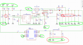
To separate GND power and GND signal and maybe we can add GND hight frequency ?
u can just confirm it if iam right or no for power GND in SEPIC


For me green GND its power GND and HF gnd and red GND its HF gnd !


if i separate those GND in pcb i should connect them on the same point with a one piste
 

Attachments

  • 1670253649432.png
    1670253649432.png
    144.7 KB · Views: 165
  • 1670253787674.png
    1670253787674.png
    79.8 KB · Views: 151

@Taihung

i separate GND to tow king : signal gnd and power gnd i think i can add H.F gnd and joint them at same point but iam not sure if it will improve my level noise or not and i can see what is the HF gnd in my sepic .


1670403907353.png


And for me the signal GND is those 9 green GND. its right or no ?

1670404158350.png


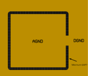
and now my question in bottom plane i do same separation or one plne GND ?
--- Updated ---

i know the answer to the question of how to deal with the grounds AGND and PGND is not that simple. That’s why this discussion continues ...
 
Last edited:

Status
Not open for further replies.

Part and Inventory Search

Welcome to EDABoard.com

Sponsor

Back
Top