Continue to Site

Welcome to EDAboard.com

Welcome to our site! EDAboard.com is an international Electronics Discussion Forum focused on EDA software, circuits, schematics, books, theory, papers, asic, pld, 8051, DSP, Network, RF, Analog Design, PCB, Service Manuals... and a whole lot more! To participate you need to register. Registration is free. Click here to register now.

100A inverter welder ( IGBTs keep blowing)

Status
Not open for further replies.

salah_edu

Junior Member level 1
Joined
Mar 28, 2008
Messages
17
Helped
0
Reputation
0
Reaction score
0
Trophy points
1,281
Activity points
1,399
Hello,

I am trying to design a 100A smps for welding , the design is two switch ( IGBT) forward converter using current transformer for feedback in primary current, the switching tranformer
is a commercialy available toroid transfomer recovred from already working welder , the issue is when i connect the board to ac mains and after a few seconds the ibgts fail without getting hot and they are shorted between ( Gate Emitter and collerctor) i tried to add a capcitor for 22nf beween Gate and emiiter to remove miller effect but i still have the same issue.
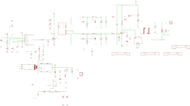
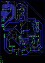
you find attached the schematic and the pcb layout.
Regards.
 

Attachments

  • layout.png
    layout.png
    80.4 KB · Views: 401
  • schematic.png
    schematic.png
    49.8 KB · Views: 472

Hi,

the PCB layout is not, how an SMPS layout should look like.

I think you still think that wide traces make a trace low impedance. But this is not the case. It lowers the DC resistance. But you don´t have DC application. You want clean, fast switching signals, without ringing, causing low EMI....
Here the "impedance" counts. Impedance is an AC measurement.

With wider traces you can not significantly lower the impedance.
* Shorter traces reduce impedance
* a return path in close proximity reduces the impedance. --> usually (and simple) done with a GND plane.

A signal path is not a way from A to B, it always includes the return path form B to A. If the retrun path is weak, lengthy or far away from the signal path, then you have bad AC performance.. resulting in bad EMI and a lot of ringing, reduced lifetime, malfunction...

I recommend to go through some Application Notes provided by semiconductor manufacturers, SMPS design documents, PCB routing videos...

Klaus
 
@salah_edu it is nice that the IGBT's are not blowing and they even worked when you shorted the secondary?
Now what you actually mean by shorting secondary ? What was the resistance of the load that you used ?

So what was the amperage that you got versus that which you wanted , how much difference?
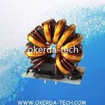
the Load is almost less than 1 Ohm and i regulate the current to get 30A in the secondry , i get now less then 10A, can i change the working frequency to get this current ? then transformer i am using look like this in the picture it is 24:8 it is used in arc welding equipement.
 

Attachments

  • téléchargement.jpg
    téléchargement.jpg
    9 KB · Views: 104

Well I'd say you just have top experiment with the turns ratio of the transformer makes a thicker wire and less turns you will get more amps.
Just make sure you don't exceed the maximum current of the driving mosfets/IGBT's
In case these are not enough you can always use more powerful IGBT's just check whether the gate capacitance is similar to the existing ones and also see whether your gate driver IC can drive them
 
Status
Not open for further replies.

Similar threads

Part and Inventory Search

Welcome to EDABoard.com

Sponsor

Back
Top