Continue to Site

Welcome to EDAboard.com

Welcome to our site! EDAboard.com is an international Electronics Discussion Forum focused on EDA software, circuits, schematics, books, theory, papers, asic, pld, 8051, DSP, Network, RF, Analog Design, PCB, Service Manuals... and a whole lot more! To participate you need to register. Registration is free. Click here to register now.

High Frequency using 8051

Status
Not open for further replies.

gauravkothari23

Advanced Member level 2
Joined
Mar 21, 2015
Messages
642
Helped
5
Reputation
10
Reaction score
4
Trophy points
1,298
Activity points
6,934
Hi all.
I need to generate high frequency output maxing 60 Khz using 8051 microcontroller.
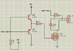
attached circuit diagram.
Software is not a problem, i would be using timer to generate high frequency.
but as per the circuit diagram, is the components selection perfect..?. will the mosfet work at frequency of 60 Khz. or can anyone recommend me some other mosfets where i can get a better performance.

- - - Updated - - -

I need to generate a square wave and drive a inductive load at 12V at high frequency.
 

Attachments

  • High Frequency.png
    High Frequency.png
    72.7 KB · Views: 196

What is the load current? IRF540 isn't suited for 5V gate control, you better use a logic level FET.

For 60 kHz switching, you need a push-pull gate driver.
 

What is the load current? IRF540 isn't suited for 5V gate control, you better use a logic level FET.

For 60 kHz switching, you need a push-pull gate driver.

Load Current is approx 2 Amps at 12V
 

There are many logic level FETs suitable for 12V 2A. I forgot an important point: The inductive load will destroy the FET if you don't connect a free-wheeling diode.
 

There are many logic level FETs suitable for 12V 2A. I forgot an important point: The inductive load will destroy the FET if you don't connect a free-wheeling diode.

I have added a free wheeling diode to inductive load, and also changed the mosfet
but still while stimulating in proteus, i am not getting pure square wave at the output, but the same at controller pin i am getting proper square wave (image attached)
 

Attachments

  • High Frequency.png
    High Frequency.png
    148.6 KB · Views: 198

The gate driver is connected wrongly. It's a complementary emitter follower, should have NPN on top and PNP on the bottom. Both emitters tied to the gate. No base resistors required, instead an optional low ohmic gate resistor.

I have added a free wheeling diode to inductive load
Not yet in the schematic.
 

You might just like a large MOSFET gate driver without
the discrete FETs, depending on the (not-stated) load
current, rise/fall times and tolerance of the part to
inductive over / undershoots. You can get 10A peak
spec parts that ought to be good for an amp or so DC
and TTL-compatible control inputs, >12V supply rating.
Look for automotive grade parts and you may find the
clamp diodes especially robust and built in.
 

The gate driver is connected wrongly. It's a complementary emitter follower, should have NPN on top and PNP on the bottom. Both emitters tied to the gate. No base resistors required, instead an optional low ohmic gate resistor.

Not yet in the schematic.

Still the things are not working. the result is the same.
(Image Attached).
Not added the diode in circuit diagram because the diode does not have a model to play, so i receive the stimulation error.
 

Attachments

  • High Frequency.png
    High Frequency.png
    174.6 KB · Views: 263
  • Like
Reactions: FvM

    FvM

    Points: 2
    Helpful Answer Positive Rating
In scope, channels should be set to DC measurement. In your setup, all channels are set to measure AC.
 

Yes, more or less.

Thanks,
But how can i do it. is my circuit diagram perfect, or need to do some changes, because while stimulating in proteus its not giving proper output.
do i need to test it in actual hardware using oscilloscope
 

Hi,

Vague descriptions:
"Perfect" --> there is no perfect. You need to live with non perfect waveform. How much tolerance in which regard can you accept? Timing, amplitude, ringing, over- or undershot, rise- fall time, duty cycle, jitter...

"its not giving proper output" --> in which regard?

Klaus
 

I skip the "perfect" square wave discussion. To get a square wave at all, you need a free-wheeling diode.
 

Thanks,
But how can i do it. is my circuit diagram perfect, or need to do some changes, because while stimulating in proteus its not giving proper output.
do i need to test it in actual hardware using oscilloscope

'Perfect' square output you will only get with resistive load. With inductor it will be different.
 

Hi all.
I have tried making the circuit and tested. but i am not getting the desired output. i am trying to drive an inductive load at 300 Khz (circuit attached) using 89S52.
what my problem is, using oscilloscope i have tested the gate pin of mosfet 11N60DM2 , which gets drive at 300 Khz, but with load or without load when the same i checked at the output, i am not getting any frequency, just a straight line of 24V.
Please let me know what changes i have to make in circuit diagram. am sure about the software part because at the gate pin i am getting 300 Khz of frequency
 

Attachments

  • High Frequency.png
    High Frequency.png
    19.4 KB · Views: 176

The schematic is OK although I would add a resistor in series with the input. Your problem is the 11N60DM2 which needs as much as 5V on its gate before it STARTS conducting. Ideally you want far more than that to ensure it turns full on .

The simplest modification I can think of is to connect Q5 collector and R2 to 24V and add another transistor at the input to drive Q5 and Q6.

Brian.

what if i change the Mosfet to STP36NF06 or i can even use IRFZ44NPBF
 

Status
Not open for further replies.

Similar threads

Part and Inventory Search

Welcome to EDABoard.com

Sponsor

Back
Top