Continue to Site

Welcome to EDAboard.com

Welcome to our site! EDAboard.com is an international Electronics Discussion Forum focused on EDA software, circuits, schematics, books, theory, papers, asic, pld, 8051, DSP, Network, RF, Analog Design, PCB, Service Manuals... and a whole lot more! To participate you need to register. Registration is free. Click here to register now.

High Freq XFMR winding optimization for DC resistance ?

Status
Not open for further replies.

CataM

Advanced Member level 4
Joined
Dec 23, 2015
Messages
1,275
Helped
314
Reputation
628
Reaction score
312
Trophy points
83
Location
Madrid, Spain
Activity points
8,409
Hi everyone,

I am talking regarding the design of the windings of a high frequency transformer. The point is to see whether or not using round untwisted conductors can get rid of the expensive Litz wire.
The optimization parameter then is the DC resistance.

It is known that due to skin effect (proximity effect between windings neglected because of the assumption of good interleaving) the AC resistance increases proportionally with the DC resistance of the winding.

For example, when the width of the equivalent rectangular winding "h" is much grater than the skin depth "δ" (h>>δ), the AC resistance has the following form (for the sake of simplicity, assume h~diameter "D" of a round conductor):

RAC=RDC*h/δ=ρ*length*4/(Π*D*δ)

As is seen, the bigger the wire, the lower the DC resistance is => the lower the AC resistance is. (D>>δ which is against the usual approach)

The downside is that as the harmonics frequency increase, the AC resistance increase because of the further reduction in skin depth.. but this is up to a certain point because the RMS current of the harmonics decrease as the frequency increase.

In conclusion, I would say this method could be a cheap alternative to the expensive Litz wire for cases where the harmonics of the current decrease below "1" in a "few" harmonics numbers. The "few" number needs to be decided according to the "h/δ" ratio and the decrease in harmonics amplitude rate.

For the case where the harmonics amplitude takes a long time to decrease below "1", the usual wire diameter selection according to skin depth should be chosen in order to prolong the number of current harmonics with amplitude>1 where Rac~Rdc.

-I would like to hear your opinion about this since this looks like a savage idea
-Did anyone experience transformers with unusually big thickness for the operating frequency they were working at ?

Thank you for your time !
 

May be I didn't get the point.

In a first order, in the "h>>δ" range the DC resistance is decreasing with 1/h² (1/cross section) while the AC resistance is decreasing with 1/h (1/circumference).

In other words, using thicker massive conductors still reduces the AC resistance, but you need fourfold copper cross section to get half Rac. The effective ratio is even worse due to increasing winding length on a given core.
 
The effective ratio is even worse due to increasing winding length on a given core.
Why would the length increase ? The length depends on the mean-length-per-turn (MLT) which is dependent on the bobbin geometry.
 

Length increase is only a side remark. I'm assuming that the number of turns is already fixed, so increasing the wire gauge means utilizing a larger percentage of the bobbin winding window, thus increasing the means length.

Mean length per turn is specified for 100 % bobbin utilization.
 
  • Like
Reactions: CataM

    CataM

    Points: 2
    Helpful Answer Positive Rating
only interleaving pri & sec works to reduce skin depth effects in HF xfmrs, parallel wires have exactly the same effect as equivalent solid ( proven extensively )

Keeping each layer to one layer of pri or sec and having a longer bobbin/core is well proven to give min losses for solid wire. We have 70kHz, 2kW Tx's on ETD49 using 0.7mm solid wire in single layers with low Rac/Rdc ...

- - - Updated - - -

to clarify, proximity effect worsens with more layers per wdg, skin effect is effectively lowered by interleaving ...
 

We have 70kHz, 2kW Tx's on ETD49 using 0.7mm solid wire in single layers with low Rac/Rdc ...
Then your XFMR is high voltage-low currents, due to the small wire you have (to keep current density within limits) - current harmonics reduce really fast in your application. Your implementation again proves what I was saying.
 

Keeping each layer to one layer of pri or sec and having a longer bobbin/core is well proven to give min losses for solid wire.
It reduces proximity effect to a minimum by achieving an almost rotational symmetrical current distribution. Ordinary skin effect rules still.
 

Proves what exactly?
O.K. maybe "prove" is not the best word that describes what I was thinking.

I meant that the method I was describing in post #1 (optimize Rdc) can be implemented as a design strategy, as the product of Easy Peasy seems to follow it.
 

You are writing in post #1 about designing a winding with D>>δ. That's not the case which the discussed winding in post #5, which has D=0.7mm and δ=0.25mm for the fundamental wave. Rac/Rdc is about 3 with pure skin effect and much more if proximity effect becomes relevant.
 

Then your XFMR is high voltage-low currents
well, yes and no, the sec wires are paralleled at the transformer terminations to give up to 50A in some apps.

The primaries are paralleled too, some Tx manufacturers have told us that the windings will not current share on the Tx for // primaries - so much they know (they are thinking in terms of R only) they haven't considered Lenz's law and the fact that currents will distribute to minimise the energy in the system - we have had so many engineers look at our Tx running at full power and obviously low temp rise ( with solid wire ) and say - how is that possible without litz? simple physics gives the answers - such that we can now design our Tx's with regard to Rdc only and know that the Rac will be ~ 15% higher worst case ...

- - - Updated - - -

Just as a point of interest, if you double the wire size, the Rac will not halve, this is because the centre of the wire is now further away from the centre of the wire of the other winding. Mathematically the AC currents in the centre of a large conductor can flow in the opposite direction to the current on the skin - really raising your AC current losses - this appears to be borne out in tests in the real world too, extra AC losses that people put down to prox effect but were in fact due to skin effect and the reversal of current as the wire size goes up ( for high driven frequencies )
 

I reviewed my theoretical electrical engineering text book about skin effect and found, that the estimation in my previous post is wrong. I took it from an apparently inappropriate estimation of the MDT calculation tool. The expectable skin effect induced Rac/Rdc for r/δ = 1.4 is about 1.1.

In so far, it's correct to say that the described configuration can give Rac near Rdc, with several prerequisites discussed by Easy peasy. But it's not possible in the D >> δ range, only for D < 3δ (and no proximity effect). Current sharing in paralleled windings is a complex thing. I'm willing to believe that it's acceptable for the discussed alternating windings topology, but I would always perform a measurement and/or AC magnetic simulation to be sure.
 

I reviewed my theoretical electrical engineering text book about skin effect and found, that the estimation in my previous post is wrong. I took it from an apparently inappropriate estimation of the MDT calculation tool. The expectable skin effect induced Rac/Rdc for r/δ = 1.4 is about 1.1.
Suggest reviewing the book again. It is not the "radius" you have to plug in, it is the diameter (assume h~diameter).
D/δ=0.7/0.25=2.8, giving Rac/Rdc=2.803 accounting Skin effect only. As you can see, it fulfills the D>>δ prediction of Rac/Rdc=2.8 (again, skin effect only).
 

Can't agree. You can make a first order estimation assuming the current concentrated in a cylindrical layer at the surface of thickness δ. Gives an Rac/Rdc ratio of 0.35²/(0.35² - 0.1²) = 1.09 for the discussed case per cross section. An exact calculation needs to evaluate Bessel functions and gives a slightly different result.

δ/D (or D/δ) can be used as a descriptive skin effect parameter, but doesn't translate directly into resistance increase.


Either if you calculate with diameter or radius, D >> δ should be considered above a ratio of 10 in my view.

If you say that Rac/Rdc should be around 3 for the discussed case, do you think that Easy peasy's observations are wrong.
 

we have had so many engineers look at our Tx running at full power and obviously low temp rise ( with solid wire ) and say - how is that possible without litz?
Of course they can not understand it unless they see the full picture. The full picture is when taking into account the current harmonics as well, like I have explained in post #1.

Power loss due to harmonics with RMS values < 1 can be neglected, so the Rac/Rdc ratio needs to be optimized at the furthest harmonic from the fundamental one which still has RMS>1, because it is there where Rac/Rdc is the highest (compared to the previous harmonics).

simple physics gives the answers - such that we can now design our Tx's with regard to Rdc only and know that the Rac will be ~ 15% higher worst case ...
How is that possible with 0.7mm thickness at 70 kHz ?
 

How is that possible with 0.7mm thickness at 70 kHz ?
As calculated in the previous post r=0.35mm, δ=0.25, cross section ratio 1.09

Unfortunately I don't understand your "harmonics" consideration at all. The basic skin depth calculation, as e.g. above, is for fundamental wave only. If you have relevant harmonic content, things become even worse.
 

You can make a first order estimation assuming the current concentrated in a cylindrical layer at the surface of thickness δ. Gives an Rac/Rdc ratio of 0.35²/(0.35² - 0.1²) = 1.09
As calculated in the previous post r=0.35mm, δ=0.25, cross section ratio 1.09
I agree with the first order estimation and hence agree with your result. But I am using the real part of Dowell expression, as explained in Optimizing the AC Resistance of Multilayer Transformer Windings with Arbitrary Current Waveforms.

Equation (1) with p=1 leaves only skin effect.
"h" I was talking about in previous posts is called "d" (lowercase "d") in that article: h=d=sqrt(pi/4)*D (fig. 1) --> assume h~D.
η1 (fig 1) =1 for N=1 and w=D~h=d

Then, eq (1) reduces to this:
Rac/Rdc=h/δ*[(sinh(2*h/δ)+sin(2*h/δ)]/[(cosh(2*h/δ)-cos(2*h/δ)] <-- only skin effect accounted

Insert that expression into a calculator for D=0.75mm and δ=0.25mm and you get Rac/Rdc=2.803

- - - Updated - - -

Unfortunately I don't understand your "harmonics" consideration at all. The basic skin depth calculation, as e.g. above, is for fundamental wave only. If you have relevant harmonic content, things become even worse.
Yes, that is the whole point. Minimize Rac via extremely minimizing Rdc so that the Rac@highest harmonic with RMS>1 is still low.
In order to do so, one needs to see the harmonic content and NOT only the Rac/Rdc @ the fundamental. Here is a quote from post #1:
The downside is that as the harmonics frequency increase, the AC resistance increase because of the further reduction in skin depth.. but this is up to a certain point because the RMS current of the harmonics decrease as the frequency increase.
 

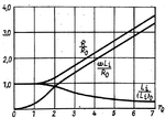
Here's the diagram from my book (K. Simonyi, Theoretische Elektrotechnik)
Skineffekt.png

The x-axis unit r0 is r/δ, wire radius divided by skin depth. R/R0 is Rac/Rdc ratio. Inner inductance is also plotted.


I could verify the R/R0 graph with an AC magnetic simulation in Quickfield, down to only a few percent deviation. I assume something's wrong with your calculation.

Searching for other references, I found this interesting article series. The last part has also links to all previous ones.
www.how2power.com/newsletters/1703/H2PowerToday1703_FocusOnMagnetics.pdf
 
  • Like
Reactions: CataM

    CataM

    Points: 2
    Helpful Answer Positive Rating
This is the problem with incomplete education ( google scanning etc ) for a single layer of pri and sec the total thickness of the wire is relevant, for interleaved, the radius is the salient factor ... until one has a complete understanding of how the geometry affects the spread of current then one is groping in the darkness ...
 

Can't agree. You can make a first order estimation assuming the current concentrated in a cylindrical layer at the surface of thickness δ. Gives an Rac/Rdc ratio of 0.35²/(0.35² - 0.1²) = 1.09 for the discussed case per cross section. An exact calculation needs to evaluate Bessel functions and gives a slightly different result.

Here is the exact calculation:

attachment.php


Here's a measurement of the AC resistance of a piece of .7mm copper wire about 1m long. This wire is not wound into a coil; it's just an isolated wire. The measurement shows Rac versus frequency from 100 Hz to 100 kHz. The DC resistance is essentially the same as at 100 Hz, and is 33.957 milliohms. The Rac at 70 kHz is 36.511 milliohms. This gives Rac/Rdc = 1.075

attachment.php


- - - Updated - - -

I agree with the first order estimation and hence agree with your result. But I am using the real part of Dowell expression, as explained in Optimizing the AC Resistance of Multilayer Transformer Windings with Arbitrary Current Waveforms.

Equation (1) with p=1 leaves only skin effect.
"h" I was talking about in previous posts is called "d" (lowercase "d") in that article: h=d=sqrt(pi/4)*D (fig. 1) --> assume h~D.
η1 (fig 1) =1 for N=1 and w=D~h=d

Then, eq (1) reduces to this:
Rac/Rdc=h/δ*[(sinh(2*h/δ)+sin(2*h/δ)]/[(cosh(2*h/δ)-cos(2*h/δ)] <-- only skin effect accounted

Insert that expression into a calculator for D=0.75mm and δ=0.25mm and you get Rac/Rdc=2.803

Equation 1 in the referenced paper says that it gives "...ac resistance of a coil with p layers".

Even if you set p to 1, the equation is still assuming that the wire is wound into a layer. The value FvM calculated is for an isolated wire, not wound into a layer. The image above shows a measurement of a .7 mm isolated wire.

The result you got of Rac/Rdc=2.803 is much too high for an isolated wire.

Here is a sweep of Rac for an isolated .7mm wire with a different scale for the sweep than in the first image:

attachment.php


Here is a sweep of Rac for the wire wound in a close wound single layer around a .58 inch diameter plastic rod:

attachment.php


Here are the two sweeps superimposed:

attachment.php


Winding into a layer greatly increases Rac/Rdc. This is due to proximity effect, which occurs even with a single layer. The value I got for Rac/Rdc for the single layer winding is 1.63. This is less than the value of 2.803 no doubt because my winding has different diameter and length.
 

Attachments

  • SkinEDA1.png
    SkinEDA1.png
    4.3 KB · Views: 353
  • SkinEDA2.png
    SkinEDA2.png
    6.6 KB · Views: 384
  • SkinEDA3.png
    SkinEDA3.png
    6.4 KB · Views: 402
  • SkinEDA4.png
    SkinEDA4.png
    6.8 KB · Views: 356
  • SkinEDA5.png
    SkinEDA5.png
    7 KB · Views: 388
Last edited:
  • Like
Reactions: FvM and CataM

    CataM

    Points: 2
    Helpful Answer Positive Rating

    FvM

    Points: 2
    Helpful Answer Positive Rating
Status
Not open for further replies.

Similar threads

Part and Inventory Search

Welcome to EDABoard.com

Sponsor

Back
Top