Continue to Site

Welcome to EDAboard.com

Welcome to our site! EDAboard.com is an international Electronics Discussion Forum focused on EDA software, circuits, schematics, books, theory, papers, asic, pld, 8051, DSP, Network, RF, Analog Design, PCB, Service Manuals... and a whole lot more! To participate you need to register. Registration is free. Click here to register now.

[SOLVED] Long distance Metal Detector schematic

Status
Not open for further replies.

Mohamed Saa

Junior Member level 1
Joined
Feb 26, 2014
Messages
15
Helped
1
Reputation
2
Reaction score
1
Trophy points
3
Activity points
98
Hello ,
can anyone help me with a circuit for a metal detector for long distance range (near 30 cm )

Regards
 

30 cm for what object?
 

Detecting an engine block at 30cm should not be too difficult, but reliably detecting a single small nail at 30cm may not even be possible.

It probably has more to do with the design of the search coil than the actual circuit how far the magnetic field extends around the search coil.

While the circuit is important, its probably much less so than the design of the search head if you expect good range.
 

Think of driving two elliptical coils in range of 50-200kHz with high VAR at resonance and measure the difference in current for series or voltage parallel tuned after balancing each to a null difference. Stepup auto transformers are allowed .

The phase shift and amplitude difference is essentially the differential impedance of each coil as it is waved past the gap between the planar coils, but measured in PPM changes in impedance.

Think how you would do this using PLL's and differential amplifiers such that the SNR is > 60dB using PLL's

Then you can detect a pin at 30cm distance. The loop diameter is most sensitive when > than the distance of the ferrous metal. that alters the Impedance of the reflected H field which loops orthogonal to the magnet wire loops. Litz wire will raise your Self Resonant Frequency (SRF) .

Can you think of a solution ?
 

As well guys as I have many hours spend building homemade detectors, let me tell you some things.

The coil is criticall - you can't ballance it propperly without an osciloscope as well a good coil is tough to build.
You have to use a high quality epoxy resign, it must be shielded to prevent the capacitive effects of the ground.

If you are not very good in building equipement I would not recomend you to start with this. You can get a good detector for several hundred dollars.

This is the best detector for the money from a very popular bulgarian manufacturer:
http://www.goldenmask.eu/

Search "Golden Mask metal detector" in youtube

If you have something very high end get XP DEUS - the best of the best.

If you need for the beach get some Minelab E-Track or a good PI detector.

All depends what you need. Tell me and I will give you the best advise.
 

These seem to be similar to US metal detectors for $250 using 18kHz.

coil must be rigid so inductance does not change with vibration. The common tap connection for both coils are driven equally, to detect a differential Impedance change. with amplitude and phase shift amplified to sound or log meter.
 
  • Like
Reactions: Em_13

    Em_13

    Points: 2
    Helpful Answer Positive Rating
The limit of a good metal detector is about 30 cm in soil with low mineralisation for 1 Euro coin. The equivalent of this is about 40- 45 cm air drtrction. This is impossible for 90% of the mass produced detectors. Building a deep detector is an art. I've spend many hours tuning the electronic and ballancing the coil of my last detector and it is deeper then my e-track.
 

i want to decrease connections and components from this circuit , as i want the output to be connected to an Arduino

also " LF357 " opamp doesn't exist near me
OJpYRmT.jpg
 
  • Like
Reactions: Gy.Sz.

    Gy.Sz.

    Points: 2
    Helpful Answer Positive Rating
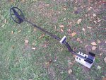
20130830_150742.jpg

This is my IDX PRO clone homemade with VDI visual discrimination:
 

    cacgod

    Points: 2
    Helpful Answer Positive Rating
i want to decrease connections and components from this circuit , as i want the output to be connected to an Arduino
You are going about this entirely the wrong way my friend.

If you have a crappy coil and weak analog circuit, a microprocessor is not going to tell you anything.

Garbage in, garbage out to eight significant digits.
 
You are going about this entirely the wrong way my friend.

If you have a crappy coil and weak analog circuit, a microprocessor is not going to tell you anything.

Garbage in, garbage out to eight significant digits.

Totally agree!!!

- - - Updated - - -

The IDX PRO clone with the VDI mod is the best that an average enthusiast can build. It is a good analogue-digital combo.
 

    cacgod

    Points: 2
    Helpful Answer Positive Rating
Status
Not open for further replies.

Similar threads

Part and Inventory Search

Welcome to EDABoard.com

Sponsor

Back
Top