Continue to Site

Welcome to EDAboard.com

Welcome to our site! EDAboard.com is an international Electronics Discussion Forum focused on EDA software, circuits, schematics, books, theory, papers, asic, pld, 8051, DSP, Network, RF, Analog Design, PCB, Service Manuals... and a whole lot more! To participate you need to register. Registration is free. Click here to register now.

lumped network does not provide matching

Status
Not open for further replies.

prateek3790

Full Member level 2
Joined
Feb 8, 2016
Messages
131
Helped
1
Reputation
2
Reaction score
1
Trophy points
18
Activity points
1,190
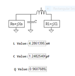
hi i am using a chip antenna in my design. i found out the input impedance of the antenna using the network analyzer now i used the matching network calculator to match this to 50 ohm. but the obtained values are not providing the matching. i can not change the design of the antenna. what modification can be done in the matching networks. any suggestions
 

If the frequency is high, and you didn't mention all the parasitics in the simulator, your matching components might need some tuning.
As a basic rule, start tuning first the series elements of the matching network.
 

Reviewing the OP's previous threads related to impedance matching, which have been dealing with extreme and effectively unmatchable impedances, I wonder if it's a regular matching problem now.
https://www.edaboard.com/threads/350427/
https://www.edaboard.com/threads/350812/

To get an idea of feasibility, can you tell the actual antenna impedance you are trying to match? Also, what does "not provide matching" exactly mean? Not meeting the calculated characteristic when implementing in real hardware, or failure in simulation?
 

no actually that simulation problem was different. this time i am using a printed antenna whose Zin=26-j40 when i found the matching network for this(@2.45 GHz to 50 ohm) it gave an L network. please see the image. on applying that matching network it should have been matched @that frequency.(expected s11 below 10 db) but it gave zin=7.6+j20.4. whay it is behaving like that. and what can be tried
 

Attachments

  • antenna_meander.PNG
    antenna_meander.PNG
    6.7 KB · Views: 118

Did you hook it up backwards? The inductor should be on the antenna side...


Aaron
 

yes i checked, it is connected properly :).
any other reason why that could be happening?
 

L-match provides impedance step-up in one direction and step-down in the other...that's why I thought you might have connected it backwards. Perhaps it is something to do with the surrounding environment? Nearby metal planes for example? Try de-soldering the L-match and just use a 0-ohm to jumper across, and re-measure Zin. The purpose is to keep the antenna's environment the same before and after matching.


regards,
Aaron
 

already did that. removed everything(from the matching network) and connected a 0 ohm as the series element to find out the input impedance of the antenna and after that did the matching.had tried for different antenna still not matched.(used different matching network for the other antenna only method was same).
 

In that case, you might have to send a photo of your work to get a better answer......


Aaron
 

Calculating backwards shows that minus sign must be missing for reactance in your calculations. Your calculated poor q-value says do not use this topology.
Simulation with ideal components to automatically find optimal topology:
1-Ideal.png
If this is for a real project must stray-losses be compensated for and lossy componets be used in simulation.
This is an example where Murata LQG15HS (0402) inductors are used for matching:
1-Murarta.png
Observe that for optimal impedance match is also topology changed when matching components are changed from ideal to lossy components.
 
Last edited:

1. why the reactance will be negative? if i assumed the zin of antenna to be the load and then attached the inductor in series(antenna side ) that will be correct implementation of the matching network. for this matching i had only three options because i could use only a pi network. see the link

https://home.sandiego.edu/~ekim/e194rfs01/jwmatcher/matcher2.html

2. how are you calculating the component values for the topology? which software you are using?

3. i know using exact calculated values will not provide the required response but i tried varying the values and saw the response the variation is not much

- - - Updated - - -

also what should be the q value (of the matching network) which can be used
 

I wonder how you arrived at zin=7.6+j20.4 for the network shown in post #4. It seem to me that the calculated LC network should give correct matching. If you are talking about real measurement versus simulation, you should indicate.
 

these all are measured values by using a network analyzer.
 

for this matching i had only three options
1. Yes it is a good online tool to evaluate a limited number of alternatives. In this case did none of theses alternatives result in optimized matching impedance.

how are you calculating the component values for the topology? which software you are using?
2. It is simulated values. The software, AnTune, can be set up for automatic optimizing but for full use of this software do it need to communicate with a VNA.

also what should be the q value
Q value is one factor among other when selecting matching network.
As resulting impedance matching in your case anyway was way off (reason below), was that maybe an even more important factor.
As you maybe saw in the online tool, similar matching circuits can result in same impedance transformation for a single frequency but resulting in different q values.
By selecting correct topology can total loss be minimized in a lossy matching network, and q factor can then play an important role.
Why it is so have too many aspects and is to much to be handled in a few lines, but an example with some common reasons why to select a higher or lower Q solution in a impedance matching circuit:

Assume a matching circuit with standard 0402 SMD reactive elements used in a typical matching network at 2.4 GHz, L,T or PI. Typical reactive values are then a few nH and a few pF.
Standard components of these values have often wide tolerances and for a typical environment for a such filter can both inductive and capacitive stray losses can be higher then the component tolerance, which can make it impossible or very lossy to implement a filter which require a high q value as correct filter values maybe not is possible to reach and if possible do it anyway need hard to find non standard component values, while a low q topology can be almost lossless and resulting in a more wide band matching, requiring less precise components, using standard E12 values.

There can also be advantages with a high q impedance matching, such as for narrow band GPS where a antenna matching network also can act as a first band pass filter suppressing cellphone TX signals located at same PCB. It can be a great SNR improvement even if it already exist a GPS SAW-filter.
A such solution do maybe require reactive components with low tolerances and low resistive losses and a more critical PCB layout, which increase total cost in production but if it also radically improves GPS performance and compatibility with nearby TX sources, can it be worth it.

I wonder how you arrived at zin=7.6+j20.4
Tuning network was most likely rotated with parallel capacitor closet to the antenna which result in 8+j40, which can be read as 7.6+j20.4 and a minor timing error.
 

Tuning network was most likely rotated with parallel capacitor closet to the antenna which result in 8+j40, which can be read as 7.6+j20.4 and a minor timing error.
This was guessed by aaron_do before (applied a different matching network than calculated). I hope we can exclude this kind of trivial faults, otherwise the discussion would be pretty pointless.

We don't know anything about the parts used for the matching network. It should be preferably 0402 size, and trace inductances and capacitances should be considered in design. Can we be sure that that the initial antenna impedance measurement was made for the correct reference plane?
 

Guess level is school work or private studies.
My feeling is that it is a constructed problem and I doubt an experienced RF designer will do basic impedance calculations with aid of online tools.
But I do still take the question seriously.

I do of course understand that the problem is nether measured or simulated correctly and it do surely not include real components or stray losses.
IRL for finding optimized network topology is also more then one single frequency point needed when tuning for a frequency range as there not is any information about how the horse-shoe is rotated or located, if there is any resonance at all.
Often should also optimized impedance topology for equipment including a radio for this freq. range take in account free space relative hand held or similar and eventual need to suppress harmonics if that is critical, which it often is for simple transmitters at 2.4 GHz.

Said that, myself do seldom have enough time to do simulations for this relative easy kind of problem, and if I do simulations is it a very simplified 10 minutes session to calculate what wave-length it can be for 2.4 GHz :)
It is faster to connect VNA and start cutting in a piece CU tape until it fits in available space.
With a bit of luck is then Smith-chart trace still visible in my VNA.
 
  • Like
Reactions: FvM

    FvM

    Points: 2
    Helpful Answer Positive Rating
sir i had applied two of the topology but did not get satisfying results. i understood the point of low q factor which might be affecting the performance. again just to make sure my input impedance is correct i will again measure the input impedance but instead of using a 0 ohm resistor as the series element i will be using capacitor near it's series resonant frequency.(hoping that it will work better).
thanks
 

I really don't understand what the problem is.

With a VNA available, you should be able to determine the actual properties of the matching network and find out why it doesn't achieve the precalculated matching. Q is an interesting point, but 2.45 GHz is small band, calculated LC network Q isn't so high that a smaller variation of L or C value (e.g. 5 or even 10 %) would give a completely wrong matching as the observed numbers indicate. Antenna Q hasn't been yet reported, there can be a problem if the antenna is very small bandwidth and it's impedance strongly affected by hand and cable effects.
 

Sir,
how antenna q is going to affect the matching.

I have already explained that how the input impedance of the antenna is measured, my only problem is that why it is not giving matching. I have already applied the matching network given in the datasheet of the antenna just to check that also is not showing matching. I know we can use the smith chart to check the behaviour of the matching network.
also if i have measured the Zin by using the 0 ohm resistor in the series it will take into account whatever the impedance is seen at the reference plane of the vna. then why do i need to reconsider the line parametrs.
 

how antenna q is going to affect the matching
It does not actually affect the matching. The simple point is if you have high Q antenna, in other words sharp resonances, a minimal change of the cable position or moving objects in the vicinity will change the antenna impedance a lot. I'm asking for the observed antenna Q to exclude similar effects.
 

Status
Not open for further replies.

Part and Inventory Search

Welcome to EDABoard.com

Sponsor

Back
Top