Continue to Site

Welcome to EDAboard.com

Welcome to our site! EDAboard.com is an international Electronics Discussion Forum focused on EDA software, circuits, schematics, books, theory, papers, asic, pld, 8051, DSP, Network, RF, Analog Design, PCB, Service Manuals... and a whole lot more! To participate you need to register. Registration is free. Click here to register now.

[SOLVED] How to reduce noise from the amplifier(s)?

Status
Not open for further replies.

MTrolle

Junior Member level 2
Joined
Jan 2, 2016
Messages
20
Helped
0
Reputation
0
Reaction score
0
Trophy points
1
Activity points
170
Hi everyone,

I am a super novice at this stuff, but I have made a "sound system". A speaker unit with 3 channels, which can listen to the 3 channels simoutanously or by demand. On the microphone unit you can setup the channels.

I want to reduce the "background" noise / noise from the amplifier. There are way too much noise, when all 3 channels are active at same time. How can I possible do this the easiest or the best way?

I hope you understand the problem and you're able to help somehow. I am very thankful for any suggestions.

Best Regards,
Michael Trolle
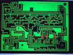
IMG_5350.jpgIMG_5351.jpgIMG_5350.jpgIMG_5351.jpg
 

I think you could start from replacing the 741s with better equivalents. IC741 is a very primitive and noisy op-amp.
You could probably settle with TL071/TL081 which are commonly used in audio applications.
 
Nice to hear, I appreciate . I am gonna order some right away to test that.

Now I found this, it should be high-end? "NE5534 OP AMP IC LOW NOISE DIL8"

Can I change other components to increase the sound quality?


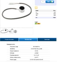
What about this electret microphone? (see attached image)
 

The NE5534 is a far better option compared to that of the ones I suggested above.
I think any electret microphone will suit your application, mainly because of a less variety available in the lower priced ones.
Just make sure that you have made the interconnections between the boards short, signals routed via shielded coaxial cables and proper grounding.
It will be better if you use the star grounding technique. This will avoid ground loops and hence reducing your overall system noise.
 
Wow. Thanks a lot for the great advice! - I am not sure, what star grounding technique is, but I'm gonna search a bit and guess it will appear. But as you say; Grounding and a quality shielded cable helps a lot.

Can you recommend other changes - for example some components that for sure are good the use?

I hope the changes will be noticeable regarding the noise. If it's allowed, then send me your email in a private message and I will give you a little reward as a thanks for the help. (If the changes do make a difference) :)
 

Hi everyone,

I am a super novice at this stuff, but I have made a "sound system". A speaker unit with 3 channels, which can listen to the 3 channels simoutanously or by demand. On the microphone unit you can setup the channels.

I want to reduce the "background" noise / noise from the amplifier. There are way too much noise, when all 3 channels are active at same time. How can I possible do this the easiest or the best way?

I hope you understand the problem and you're able to help somehow. I am very thankful for any suggestions.

Best Regards,
Michael Trolle
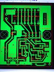
View attachment 124691View attachment 124692View attachment 124691View attachment 124692

If it is not noisey before you connect the 3 channels it means that your amplifier is OK. You have to identify which channel brings the noise and to deal with it only. It could be earthing problem.
 

Seems like my last message wasen't sent.

Well I would like to change any component to the best ones to achieve the best possible sound quality.

If you can help me and I find the results good I will personally reward you. Send me your email in a private message if you believe you can help me :))

I still thank you a lot for the help so far - I am so excited to test the NE5534.
 

Hi Vbase,

Well it is noisy when 1 channel is active, but it gets 3x worse when all 3 are active at same time. So I believe changing from LM741 to NE5534 will change a lot? But I take any advice, that can improve the sound.

The grounding / earthing is done correctly, but the hum/noisy is still there.
 

You did not describe the "background noise". Is it high frequency hiss, low frequency hum, low frequency rumbling or acoustical feedback howling?

The design of the 741 opamp is 47 years old. It cannot produce high audio frequencies and was never intended for audio (maybe for a telephone?) so it is noisy with hiss and rumbling.
Your circuit also shows a cheap old little LM380 power amplifier that also produces plenty of hiss and rumbling noise but a better replacement will have different pins and will not fit on the circuit board.

The circuit has a high frequency filter directly following the volume control that cuts frequencies above 457Hz when the volume control is halfway. It cuts most hiss and high frequency squealing feedback.

Acousical feedback howling occurs when the microphone can hear the speaker and causes sounds to go around and around (out the speaker, through the air, into the microphone, amplified and out the speaker again, over and over). It is stopped when the mic and speaker are far apart and when the volume control is turned down.
 
Hi Vbase,

Well it is noisy when 1 channel is active, but it gets 3x worse when all 3 are active at same time. So I believe changing from LM741 to NE5534 will change a lot? But I take any advice, that can improve the sound.

The grounding / earthing is done correctly, but the hum/noisy is still there.

Maybe I wasn't clear: If it is not noisey when the 3 channels aren't connected at all it means that your amplifier is OK, and it is likely earthing problem.
 
Low frequency hum can be caused when your wires from the microphones are not shielded audio cables and act like antennas to pickup electricity hum that is all around you.
 

You did not describe the "background noise". Is it high frequency hiss, low frequency hum, low frequency rumbling or acoustical feedback howling?

The design of the 741 opamp is 47 years old. It cannot produce high audio frequencies and was never intended for audio (maybe for a telephone?) so it is noisy with hiss and rumbling.
Your circuit also shows a cheap old little LM380 power amplifier that also produces plenty of hiss and rumbling noise but a better replacement will have different pins and will not fit on the circuit board.

The circuit has a high frequency filter directly following the volume control that cuts frequencies above 457Hz when the volume control is halfway. It cuts most hiss and high frequency squealing feedback.

Acousical feedback howling occurs when the microphone can hear the speaker and causes sounds to go around and around (out the speaker, through the air, into the microphone, amplified and out the speaker again, over and over). It is stopped when the mic and speaker are far apart and when the volume control is turned down.

Thanks a lot for the answer.

I am a 100% sure it is not acoustical feedback, but that do happens, when the microphone is too close to the speaker.

Can you recommend a change for the LM380? Then I will just change the circuit board - I believe that is possible? :)

I am not sure which kind of noise it is. I guess it's mostly low frequency hum or rumbling.

Can I do anything with that high frequency filter you're talking about?

(Maybe I can record the sound, so you can hear it? :D)

Best Regards,
Michael

Thank you all so much for the help so far!
 

Hi,

It seems you use serially connected electrolytic capacitors in the signal path. I personally try avoid this with high quality audio circuits.
They may cause noise.

They are polarised. Do you expect DC? If yes, are they connected the correct way? Try to use audio style capacitors. Best are film capacitors, but they are big and expensive. Maybe try a single one if it really brings a benefit.

Are the shields (ground) of the input signals connected elsewhere? Maybe causing ground loops via earth signal?

Can you post a true schematic... It may be easier to read than the pcb layout.

Klaus
 

Low frequency hum can be caused when your wires from the microphones are not shielded audio cables and act like antennas to pickup electricity hum that is all around you.

If I do not connect a microphone, but just turn up the volume on the speaker unit, then the noise appear aswell and everytime I activate 1 more channel the noise gets a lot louder. It's like it is catching some kind of a radio channel sometimes I have a recording, where I can hear a radio channel :D

I have attached a recording. It starts like this: Low volume(no channels active), volume goes to max and I activate channels 1 by 1 untill total of 3 are active, then I deactivate 1 by 1 and turn down volume.

There is no microphone attached in the recording and the speaker is catching some radio channel signals / music.View attachment Sound-recording.m4a.zip

- - - Updated - - -

Hi,

It seems you use serially connected electrolytic capacitors in the signal path. I personally try avoid this with high quality audio circuits.
They may cause noise.

They are polarised. Do you expect DC? If yes, are they connected the correct way? Try to use audio style capacitors. Best are film capacitors, but they are big and expensive. Maybe try a single one if it really brings a benefit.

Are the shields (ground) of the input signals connected elsewhere? Maybe causing ground loops via earth signal?

Can you post a true schematic... It may be easier to read than the pcb layout.

Klaus

Hi Klaus,

Are you from Denmark? (You're name look danish).

DC? The power source? Yes it is DC.

Serially connected sounds correct. I know that the "system" is installed serially.

I have no idea, how I should avoid the serial connection of the electrolytic capacitors. I am really not that technical :D

But if anyone here can make an identical system, but with better sound and on same size circuit board, then I happily pay you. I just need to know how much before you start doing it.

The ground goes from the circuit boards "GND" to the "metal-case" which the circuit board is installed in. On the powersupply the ground is also attached to the "-". There is no grounding on the microphone as far as I know.

I am not sure how I possibly could post a schematic - that has not really been made based on the design. Well if "Sprint-Layout" can do it, it is no problem :)

(I have posted a zip, with an audio recording in which you can hear the noise problems - notice there is no microphone attached in the recording, only the speaker)
 

Can you recommend a change for the LM380? Then I will just change the circuit board - I believe that is possible? :)

Do you require the same power delivery?
If you can settle with a higher power delivery, then you can use the TDA2030, which is very common. It's packaging is different, and may require heatsinking if you decide to increase the power to be dumped in the load.
 

Do you require the same power delivery?
If you can settle with a higher power delivery, then you can use the TDA2030, which is very common. It's packaging is different, and may require heatsinking if you decide to increase the power to be dumped in the load.

I want to change anything, that can make the sound better - also the cost of the components doesn't matter much. Well I don't have money for some NASA components :D

There should be room for minor heat sinks.

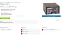
If it can help out anything I am using this power supply(I experienced that some power supplies made noise aswell, this one seemed best): Mascot 6823 (see attachment).


The most important things are; the circuit board still fit in the box and the system is simple like now.
 

In any system, the SNR (Signal to Noise Ratio) is highest at the input. It keeps on degrading as we go through the stages of the amplifier, and hence some amount of noise is added in every stage. Replacing the 741s with NE5534 will onviously yeild a higher SNR.
So, let's see how the replacement of 741s works out, and then you will be able to figure out the amount of noise generated in the power amp.
Whether it is acceptable or not? Whether you need to re design the power stage again? I think things should be more clear after the replacements.

That sounds good I will try that then and return with the results. I believe I can have the components on the 5th - so stay tuned :D

I have read that WIMA 100nf capacitors are good for audio is that true? Then I order some of them at same time.

NE5534AP or NE5534P - which one is best?
 
Last edited:

Hi,

I should clarify some things:
I personally don't like (standard) electrolytic capacitors in an audio signal path.
(--> I'm not talking about power supply)
With "serially connected" I mean the capacitors act like an LPF, or for DC blocking.
If they should act as an LPF, then they are meant to block low frequency AC and DC. But they are not made for AC...so if there is AC it will cause distortions.
If they should act for DC blocking, then you should check correct polarity.
There are special - low noise - audio type electrolytic capacitors. And there are special non polarised electrolytic audio caoacitors.

and the speaker is catching some radio channel signals / music
This sounds like some HF related problem.
Try to install HF RC filters at each input. It's hard to recommend values, because I don't know your source impedance.
You could play with 10p to 1000p at the input and check if the sound is still OK.especially the higher audio frequencies.
 

Hi,

I should clarify some things:
I personally don't like (standard) electrolytic capacitors in an audio signal path.
(--> I'm not talking about power supply)
With "serially connected" I mean the capacitors act like an LPF, or for DC blocking.
If they should act as an LPF, then they are meant to block low frequency AC and DC. But they are not made for AC...so if there is AC it will cause distortions.
If they should act for DC blocking, then you should check correct polarity.
There are special - low noise - audio type electrolytic capacitors. And there are special non polarised electrolytic audio caoacitors.


This sounds like some HF related problem.
Try to install HF RC filters at each input. It's hard to recommend values, because I don't know your source impedance.
You could play with 10p to 1000p at the input and check if the sound is still OK.especially the higher audio frequencies.

Hi Klaus,

Can you give me some specific recommendations regarding the audio type electrolytic capacitors and for the non polarized aswell?

Again, can you recommend some specific HF RC Filters? (A brand or something). Thanks a lot for your help :)
 

Status
Not open for further replies.

Part and Inventory Search

Welcome to EDABoard.com

Sponsor

Back
Top