Continue to Site

Welcome to EDAboard.com

Welcome to our site! EDAboard.com is an international Electronics Discussion Forum focused on EDA software, circuits, schematics, books, theory, papers, asic, pld, 8051, DSP, Network, RF, Analog Design, PCB, Service Manuals... and a whole lot more! To participate you need to register. Registration is free. Click here to register now.

Enabling or Disabling the pin in AT89C51 in C

Status
Not open for further replies.

Eshal

Advanced Member level 1
Joined
Aug 29, 2012
Messages
470
Helped
16
Reputation
32
Reaction score
15
Trophy points
1,298
Location
Nowhere :)
Activity points
5,149
Hello experts,

My situation is,
I have connected an LDR to the pin P2.0. And I want to disable all other pins of the controller until P2.0 gets equal to the 5V. Where, 5V=Vcc.

How to do this using C language?

Thank you very much.
 

How you connect ldr to 8051?
I mean directly or using comparator??
 
  • Like
Reactions: Eshal

    Eshal

    Points: 2
    Helpful Answer Positive Rating
Using comparator LM339. Well it doesn't matter which comparator I use. Just using comparator.
 

For 339 external pullup resistor of 10k is needed at output check datasheet of 339.
Use 358 if you want to inteface only one ldr to 8051 and it doesn't required pullup resistor.
Regards,
Hamid s.
 

This is not the answer to my question. First read my post then reply.
I am not asking for circuit designing. I am asking how to disable all other pins of 8051 until I get P2.0 to be equal 5V.

I have connected 10K pull up resistor.
 

This is not the answer to my question. First read my post then reply.
I believe you could have asked a clearer question. The "5V" point is at least misleading, 8051 logic threshold is somewhere between 1 and 2 V rather than 5V.

What do you mean exactly with disable? 8051 GPIOs have no tri-state feature, they are either pulled low or floating, most with weak pull-up.

Can we conclude that "disable" actually means set to high level? It's easy to write '1' to all pins.

Like

Code C - [expand]
1
2
3
4
5
6
7
8
9
if (P2_0) {
  P0 = 0xff;
  P1 = 0xff;
  P2 = 0xff;
}
else
{
  // perform regular GPIO control
}

 
  • Like
Reactions: Eshal

    Eshal

    Points: 2
    Helpful Answer Positive Rating
8051 doesn't have any registers for setting the direction of it's ports. Unlike the DDR register for AVR and TRIS register for PIC. If you need to use a port pin on the 8051 as an input, you simply need to write logic 1 to that particular pin.

This piece of code should work if you wire your comparator as an Inverting comparator (Output Low when Input > Preset Value)


Code C - [expand]
1
2
3
4
5
6
7
8
9
10
11
12
13
14
#include <reg51.h>
int main(){
P2 |= 0x01;   // Set P2.0 as input
while(1){
 
if((P2 & 0x01) == 0x01)   // Input < Preset
{
  // Code to be performed when value below preset
}
else   // Input > Preset
{
  // Code to be performed when value above preset
}
}

 
Last edited by a moderator:
  • Like
Reactions: Eshal

    Eshal

    Points: 2
    Helpful Answer Positive Rating
@ThirunavukkarasuThoondi
I am using comparator so its mean my output of LDR is digital.

@FvM and @pradhan.rachit
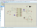
Now you listen what is I want to do with my circuit. Here is the diagram below of my circuit.
Capture.PNG

The output of comparator U2:A is the output of LDR. And the output of comparator U2:B is the output of the IR sensor (I am using button instead of IR sensor).

The idea is when the LDR is dark then output LED at P1.0 is on. If LDR is lighted then output LED at P1.0 is off. Now, you have understood how LDR connection will work. Now move to the IR sensor connection.

When a button is pressed then output LED at P1.0 is on otherwise it should remain off.
Now, you have understood how the IR sensor connection will work. Now move the combine effect of the LDR and IR sensor (Remember I am using button in place of IR sensor for simulation)

Now, the IR sensor connection at P2.1 work by pressing button i.e. it should turn on LED at P1.0 if and only if the output of the LDR comparator is high i.e. P2.0 is high otherwise IR sensor should not be able to turn on the LED at P1.0.
 

Now, the IR sensor connection at P2.1 work by pressing button i.e. it should turn on LED at P1.0 if and only if the output of the LDR comparator is high i.e. P2.0 is high otherwise IR sensor should not be able to turn on the LED at P1.0.

This code is written considering that the quoted text is your final condition.


Code C - [expand]
1
2
3
4
5
6
7
8
9
10
11
12
13
14
15
16
17
#include <reg51.h>
int main(){
P2 |= 0x01;   // Set P2.0 and P2.1 as input
P1 &= 0x00;  // Clear P1
 
while(1){
 
if((P2_1 == 0)&&(P2_0 == 1)) // Button Pressed, LDR dark
{
   P1 |= 0x01; // LED on
}
else
{
  P1 &= 0xFE; // LED off
}
 
}

 
Last edited by a moderator:
  • Like
Reactions: Eshal

    Eshal

    Points: 2
    Helpful Answer Positive Rating
Sorry but I don't see any code. It is totally blank. I am online using mobile phone. On other threads I can see codes. But here I can't see any code. :-/

- - - Updated - - -

@pradhan.rachit
I am very much obliged to you for your kindness. I will first how did you do this. If I stuck then I will ask you and I am sure you will always be here to help me. Thank you for your reply.

Regards
Princess
 

Sorry but I don't see any code. It is totally blank. I am online using mobile phone. On other threads I can see codes. But here I can't see any code. :-/

A moderator reworked the code formatting in post #10. Please tell us whether your device now displays the code.
 
  • Like
Reactions: Eshal

    Eshal

    Points: 2
    Helpful Answer Positive Rating
There is a mistake on line 3, it should be P2 |= 0x03; instead of P2 |= 0x01.
 
  • Like
Reactions: Eshal

    Eshal

    Points: 2
    Helpful Answer Positive Rating
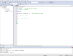
Yeah... I have already corrected it. But When I tried the code then I received two error. One was the closing bracket of main function. And other was about P2_1. Look at the picture.
Capture.PNG

Can you rectify the mistake pradhan for me?

First tell me this then I will ask further about the circuit. I have a question. But this problem first.

Thank you very much.

Regards,
Princess

- - - Updated - - -

@BradtheRad
Sir, I can now see the code easily. Thank you for your attention on the spot. :)
 

@Pradhan.rachit
Ohh yes, my bad. I could not figured out right syntax. :) Thanks.

Just polling for comparator outputs at the port. The button depicts the state of an IR LED as per his diagram.
First of all, I am not a boy. I am a girl. So it should be like "Just polling for comparator outputs at the port. The button depicts the state of an IR LED as per her diagram." OK?

And finally, I would like to know what does pic.programmer said? I have not understood his words, debounce the switch. And what did you reply? I have not gotten your reply to him too. :(

- - - Updated - - -

@Pradhan.rachit
Hello dear :wink: lol

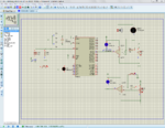
See below the attachment. When LDR is dark and at the same time button is pressed too but the LED at P1.0 is not glowing in any condition whether LDR is dark and button is not pressed, whether LDR is not dark and button is not pressed, whether LDR is not dark and button pressed and finally LDR is dark and button pressed. In any of the said 4 conditions the LED at P1.0 is not glowing.
Capture.PNG

The above attachment is the case when LDR is dark and button is pressed.

Can you also help me by writing the code in decimal format? Actually, I do understand hex (i.e. 0x00 etc) but decimal is quite easy to understand. And also I don't know what is |= and &=.

Thank you.

Regards,
Princess
 

Please zip and post the project files and Proteus file.
 

@Pradhan.rachit
And also I don't know what is |= and &=.

Correct line 8 as:
if((P2^1 == 0)&&(P2^0 == 0))

P1 |= 0x01 means P1 = P1 | 0x01 i.e. P1 is ORed with hex value 01, Binary 0000 0001 LED ON
P1 &= 0xFE means P1 = P1 & 0xFE i.e. P1 is ANDed with hex value FE, Binary 1111 1110 LED OFF
 
  • Like
Reactions: Eshal

    Eshal

    Points: 2
    Helpful Answer Positive Rating
Status
Not open for further replies.

Similar threads

Part and Inventory Search

Welcome to EDABoard.com

Sponsor

Back
Top