- Joined
- Jan 22, 2008
- Messages
- 52,857
- Helped
- 14,777
- Reputation
- 29,839
- Reaction score
- 14,215
- Trophy points
- 1,393
- Location
- Bochum, Germany
- Activity points
- 300,014
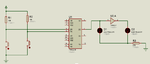
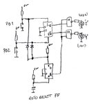
I read post #1 so that both buttons pressed must not be handled. Thus the simped RS NAND latch should be OK.
https://en.wikipedia.org/wiki/Flip-flop_(electronics)#SR_NAND_latch
https://en.wikipedia.org/wiki/Flip-flop_(electronics)#SR_NAND_latch