Eshal
Advanced Member level 1

- Joined
- Aug 29, 2012
- Messages
- 470
- Helped
- 16
- Reputation
- 32
- Reaction score
- 15
- Trophy points
- 1,298
- Location
- Nowhere :)
- Activity points
- 5,149
Hello experts!
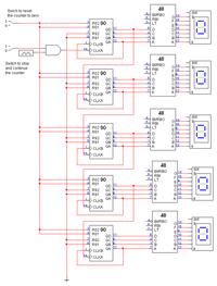
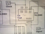
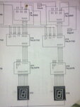
I have a lab project of 3-digit frequency counter. But we have given a circuit of 4-digit frequency counter circuit diagram. I am posting the given schematic here.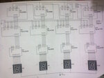
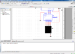
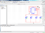
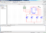
I have designed it in multisim. Here is my multisim snapshots.

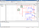
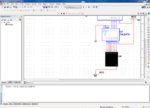
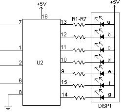
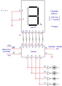
I have built the circuit in multisim same as given in the schematic but it is not working. I am using 7-segment LED display common cathode. Its mean, I will have to connect CK pin to 5v. Right?
You can see multisim is running but nothing is displaying on the 7-segment LED.
Actually, I don't know what frequency should I given on the clock. I think, it should be 1Hz.
XFG1 is the clock signal
XFG2 is the signal of unknown frequency (signal, which frequency is to be determined)
Anybody help?
Regards,
Princess
I have a lab project of 3-digit frequency counter. But we have given a circuit of 4-digit frequency counter circuit diagram. I am posting the given schematic here.


I have designed it in multisim. Here is my multisim snapshots.


I have built the circuit in multisim same as given in the schematic but it is not working. I am using 7-segment LED display common cathode. Its mean, I will have to connect CK pin to 5v. Right?
You can see multisim is running but nothing is displaying on the 7-segment LED.
Actually, I don't know what frequency should I given on the clock. I think, it should be 1Hz.
XFG1 is the clock signal
XFG2 is the signal of unknown frequency (signal, which frequency is to be determined)
Anybody help?
Regards,
Princess


