Continue to Site

Welcome to EDAboard.com

Welcome to our site! EDAboard.com is an international Electronics Discussion Forum focused on EDA software, circuits, schematics, books, theory, papers, asic, pld, 8051, DSP, Network, RF, Analog Design, PCB, Service Manuals... and a whole lot more! To participate you need to register. Registration is free. Click here to register now.

I want to build a controllable high voltage power supply

Status
Not open for further replies.

doom3cool3

Newbie level 6
Newbie level 6
Joined
Dec 26, 2012
Messages
11
Helped
0
Reputation
0
Reaction score
2
Trophy points
1,281
Activity points
1,371
Hello,just as the title,I want to build a controllable high voltage power supply,which means I can adjust the input and get the different output high voltage.

I use the variac as input which can operate in a range of 0~260VAC with 5A,then connect with a Cockcroft–Walton circuit.I used 1N4007 as the diodes and 104/1KV as capacitors.
And I made it 10 stages.

Will this way work? Or will it be danger ?

Thanks for giving me some idea.
 

Yes, it's workable. The variac will make it especially convenient to 'dial a volt level'.

The Cockcroft-Walton design is a popular choice because no single component carries more than the incoming supply V.

The '104' label works out to .1 uF. Depending on how much load you expect to attach, this could be undersize. You may get 1 kV through 20 Mohm. The first load capacitor will have 258V, but the final load capacitor will only have 27V on it.

Without any load, you would ordinarily expect more than 250 V on each of the ten load capacitors. Totalling 2.5 or 2.6 kV.

Therefore to get increased output, consider using 1 uF caps. Or you can parallel two or three of the .1 uF capacitors. Etc.

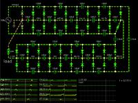
One of my favorite pastimes is to construct simulations of voltage multipliers.
Here's a screenshot of a 10-stage C-W:


The scope traces show charge level on the ten load capacitors (starting with the one next to the ground icon).

The load is at the left, connected across the first and last load capacitors.

My setup is similar but not exactly the same as commonly depicted. There is no need for a ground connection to the AC supply. There is no need for initial capacitors at each supply line.

My setup is subject to revision, such as adding a duplicate section, adding a section at negative polarity, etc.
 

If it works, its very dangerous !!!! Be carefull and take all the precautions!!!!!
 
U can also use the flyback transformer in the old TVs or computer monitors
it can give up to 24Kv and there are a lot of circuits that control it
HTML:
http://leoricksimon.blogspot.com/2007/05/flyback-driver.html
HTML:
http://lifters.online.fr/lifters/labhvps/tht.htm

Regards,
Hz
 

Thanks so much you guy.
Another question is can I connect a transformer after variac so that it can step up the voltage again?
That's means when I adjust the variac,the new transformer will output another higher voltage.
If I can,how should I wind this kind of transformer.

Thanks again!
 

What device you plan to make 220V at 5A gives lots of power. If you want higher ammount of current in output stage use transformer. Maybe you can get better answer if you describe purpose of this device.
 

As the first post in this discussion,I want to build a controllable high voltage power supply,which means I can adjust the input and get the different output high voltage.

I use the variac as input which can operate in a range of 0~260VAC with 5A,then connect with a Cockcroft–Walton circuit.I used 1N4007 as the diodes and 104/1KV as capacitors.

In result I want to get at least 10KV,but the variac's maximum output is 260VAC,in other word I must make the Cockcroft–Walton circuit about 50 stages.

I'm searching a way that i do not need to make so many stages in Cockcroft–Walton circuit,so I need to raise the voltage input which is larger than 260VAC.
 
You should use diodes and capacitors with higher voltage ratings. 1N4007 is not good for this job, also cap up to 1KV is not appropriate for your needs.

You can use voltage adjusting autotransformer or standard prim/sec transformer with multiple taps or core adjustment.

For this you need only one part - device, its transformer (Variac with appropriate voltage range). If your Variac have 0-260V range you can use additional appropriate transformer on Variac output to get higher voltages.


300px-Tapped_autotransformer.svg.png
step_up_auto.gif
 
Last edited:

Thanks so much!

So what kind of transformer should I choose to add after variac? The picture you show me looks like the the transformer has one coil like variac.
 
Yes on pictures its autotransformer. After autotransformer you can use transformer pri/sec coils with appropriate coil ratio. Primar for 260V and secundar 2600V (1:10).
 

Thanks again

I have tested that when variac input up to 200VAC,the 10 stages Cockcroft–Walton circuit shown that the output voltage had dropped from its theoretical value,which is 200*10*1.4=2800V

So if I still use the new transformer after variac,the output voltage may not be multiplied as well as I want.

Do you guys have any idea?

Thanks for giving me so much help
 

I would perservere with a Cockcroft Walton multiplier. The thing to note is that the capacitors carry all the ripple current for the subsequent stages. If you increase the first capacitor times ten, you reduce the voltage drop across it by ten times, and pass on a higher voltage pulse to the next stages. . .So the values should be 10C,9C,8C. . Its years ago when I built 10 stage multiplier with 40V input, I seem to remember that the first capacitors were 1000 micro farads (for a 400V 100 mA PSU).
Frank
 
Last edited:

Thanks again
So if I still use the new transformer after variac,the output voltage may not be multiplied as well as I want.

I disagree with this. You can get best and finest voltage regulation with transformer. If you regulate voltage on primar this will be reflected to secundar voltage. The problem is in that you need one additional transformer, which is calculated to your needs.
 

Thanks so much.

I mean the output voltage from Cockcroft–Walton circuit,not the iron core transformer.

Because when variac output 200VAC to the Cockcroft–Walton circuit,the final voltage had not been multiplied as the theoretical value.

So I guess any voltage higher than 200VAC input would not let this circuit multiply so much either.

Thanks guy and wish you happy new year!


Cockcroft-Walton design dont use transformer. At this design its point in that to multiple voltage without transformer. :):wink:

With Cockcroft-Walton design you can get very high voltages, that no problem, but current is very small. Use appropriate voltage ratings for capacitors and diodes.

What current you need on HV output? What is purpose and role of device?
 

Thanks man!

I want to supply at most 15KV DC voltage. Temporarily not care the current.

I trying to make an ion wind blower to analysis the relationship between air velocity and voltage,so I need to build a adjustable high voltage supply that can offer me different voltage.
And most important I'm not studied electrical engineering in college,I'm a layman in this field.So I'm searching a very simple circuit to help me build a high voltage power supply.

It seems that Cockcroft–Walton circuit is my last plan.

So what kind of "source" should I use before the Cockcroft–Walton circuit? Its voltage must can be adjustable like variac.
 

You can use car bobine (ignition coil). Usually output voltage is based to car manufacturer model, but most from 12KV to 20KV. Ignition coil works on input 12V, and regulating that input voltage you can regulate output voltage. You need switching circuit for this.

You can search HV Tesla transformer (coil) design.

I think only right way is with transformer.


Check Danyk Site HV section:
**broken link removed**


**broken link removed**


Switch to English or use Google translator. :)
 

Temporarily not care the current.
Doesn't sound resonable. Current definitely matters. It decides about the feasibility of specific solutions, also about the eletrical hazards brought up by your design.

I doubt that it's responsible to support the project unless you're clearly aware of the safety risks.
 

Thanks a lot you guy.

I say "Temporarily". Because some research indicated the current don't effect on the ion wind velocity much,also Cockcroft–Walton circuit output very small current.And I will step by step to fix this circuit to completely safe and stable

All I have to worry about now is the variac.
 

Because some research indicated the current don't effect on the ion wind velocity much
I overlooked your reference to ionic wind in the previous post (the first application related hint in your thread). I agree that it somehow restricts the current range of interest.

I won't agree in general that ion current doesn't affect the generated wind. But in most cases, the saturation current of field ionization sources will be a limiting factor.

To design a cascade multiplier, e.g. select capacitor values, it's nevertheless necessary to assume a rated output current.
 

Status
Not open for further replies.

Similar threads

Part and Inventory Search

Welcome to EDABoard.com

Sponsor

Back
Top