Continue to Site

Welcome to EDAboard.com

Welcome to our site! EDAboard.com is an international Electronics Discussion Forum focused on EDA software, circuits, schematics, books, theory, papers, asic, pld, 8051, DSP, Network, RF, Analog Design, PCB, Service Manuals... and a whole lot more! To participate you need to register. Registration is free. Click here to register now.

I want to start ARM with lpc1768 cortex M3

Status
Not open for further replies.
Is the SystemCoreClock define correctly when you call
Code:
SysTick_Config(SystemCoreClock/1000 - 1); /* Generate interrupt each 1 ms   */

You can try to use
Code:
/* Update SystemCoreClock according to register settings */
	SystemCoreClockUpdate();

There is also no need to use -1, just SystemCoreClock/1000

How much delay do you get instead of 300ms?
 
How much delay do you get instead of 300ms?
thanks my friend alexan for your answer
How is the default value of SystemCoreClock?
I get about 2.5s delay instead ,you can see it in this picture
what should I do now?
l1624_delay1.png
 

SystemCoreClock represents the clock frequency of your mcu and it should be automatically calculated.

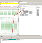
Find it in the symbol window in the system_LPCxx.C file and add it to th watch window to read the value

For example this is 48MHz
SystemCoreClock.gif

Also open the uvision clock window to see if you have set the clock correctly
LPC_clock.gif
 
thank you very much my friend alexan
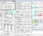
I changed clock adjustment similar LedBlinky example from cmsis library (look below picture),but CCLK and another clock did't changed!!!
periferal.PNG
 

There is some startup code that needs to be executed, did you run the code to reach main?
 

There is some startup code that needs to be executed, did you run the code to reach main?
when I changed them and then run program or run program and then change them, all of the clock back to the first state!!!(look picture)
cclk.PNG
 
  • Like
Reactions: PA3040

    PA3040

    Points: 2
    Helpful Answer Positive Rating
I can't figure out what is wrong in your project, it shows 0 for the main clock and I'm missing all the included files too so I have to use my own which are the default ones.

I would suggest you start with the gpio example in the code bundle and change M=50 N=2 for PLL0 in system_LPC17xx.c to get 100MHz
It is usually a good idea to make a copy of this system and startup file in your project folder then add it to the project and change it.

- - - Updated - - -

Here is the GPIO example from the code bundle, I have copied the startup and system in the project folder and changed then pll setting to get 100MHz.
Now just change the code.
 

Attachments

  • GPIO.zip
    124.8 KB · Views: 98
I would suggest you start with the gpio example in the code bundle and change M=50 N=2 for PLL0 in system_LPC17xx.c to get 100MHz
It is usually a good idea to make a copy of this system and startup file in your project folder then add it to the project and change it.

.
thank you
can we change PLL0 from peripherals tab in keil or just change M&N from system_LPC17xx.c ??
 

you change it from system_LPC17xx.c , use the wizard functionality of uvision.
I have already set it to 100MHZ, do you want t a different setting?
 

Here is the GPIO example from the code bundle, I have copied the startup and system in the project folder and changed then pll setting to get 100MHz.
Now just change the code.
thanks for changed pll setting for me
Did you just change " PLL0CFG_Val" to 0x00020031 ?
why you choose this number for M&N?
 

I have changed M and N value of PLL0 in system_LPC17xx.c based on the excel calculator sheet provided in the link of my previous post system_LPC17xx.c
 
double click the system_LPC17xx.c in the left panel so that it opens in the right panel.
In the lower part of the window select the wizard tab.
Access the PLL0 settings and change them and then save the file.

If you have changed the system_LPC17xx.c content manually then (in text) start fresh from the zip I have provided

uvision_wizard.gif
 
tnx my friend, I executed gpio example in the code bundle and I changed M&N(m=50,n=3) from configuration wizard but my clock didn't change :-(
not change.PNG
 

The equation is F_cco0 = (2 * M * F_in) / N

This gives the PLL output that should be in the range 275 MHz to 550 MHz
Then this is divided by CCLKSEL: Divide Value for CPU Clock from PLL0 (it is in CPU Clock Configuration Register in the wizard)

Here is another version, it uses M=100, N=6 and CCLKSEL=4

(2 * 100 * 12Mhz) /6 = 400MHz

400MHz/ 4 = 100MHz
 

Attachments

  • pll.zip
    151.4 KB · Views: 88
we should change M&N before Debugging or start debug and change them ??
 

You should change the values and save them before compile so that they are stored in the hex (axf) file.
If you want to change them on the fly in your code while it the mcu is running there is a specific process you should follow I think but you have to check the user manual.
 
Before any thing I am thankful for helping me in order to solve my problems. I learned this part now I want to work at the rest of the program.
How dose this line make 1ms?
Code:
 SysTick_Config(SystemCoreClock/1000 - 1); /* Generate interrupt each 1 ms   */
 

Status
Not open for further replies.

Similar threads

Part and Inventory Search

Welcome to EDABoard.com

Sponsor

Back
Top