Continue to Site

Welcome to EDAboard.com

Welcome to our site! EDAboard.com is an international Electronics Discussion Forum focused on EDA software, circuits, schematics, books, theory, papers, asic, pld, 8051, DSP, Network, RF, Analog Design, PCB, Service Manuals... and a whole lot more! To participate you need to register. Registration is free. Click here to register now.

(Arduino) What sensor to detect electrical pulses?

Status
Not open for further replies.

cntntn

Junior Member level 1
Joined
Mar 8, 2012
Messages
18
Helped
0
Reputation
0
Reaction score
0
Trophy points
1,281
Activity points
1,403
Hi,
With my Arduino UNO board I need to detect how many pulse of electric current come to a spark plug cap, when the engine works.
There are any sensor can do that ?
The bigger problem (I think) is the voltage of current (can be higher then that of 20000v), but most of the RPM counter on bike works in this way, so there must be a way...

Thanks to all who help me :smile:
 

thanks for reply.
But I need some explanations:

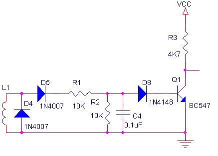
That's the circuit to clean the pulses,

38_1244969036.jpg


VCC is the input of current? can I connect it on my arduino board (powered by 12v transformer) ?
Where i have to connect that circuit to send pulse to arduino?

thanks
 

Try to use this modified circuit.
I have replaced the first 1N4007 diode with a 5V6 zenner diode, and the capacitor value = 1nF, no need for the last diode (D8).
 

Attachments

  • sensor board.png
    sensor board.png
    71 KB · Views: 238
Try to use this modified circuit.
I have replaced the first 1N4007 diode with a 5V6 zenner diode, and the capacitor value = 1nF, no need for the last diode (D8).

Thanks, but I have some questions:
What diode i have to use in position D2, and what kind of transistor T1 ?
Can I made the inductor? If I can, how big should be the copper wire?

thanks for your support :-D
 

You may use any small signal NPN transistor, BC107, BC171, BC173, BC547, 2N3904, 2N2222… also no special requirements for the D2 diode: 1N4007, 1N4148.

---------- Post added at 00:41 ---------- Previous post was at 00:38 ----------

Same idea here:
https://www.sportdevices.com/rpm_readings/index.htm
 
  • Like
Reactions: cntntn

    cntntn

    Points: 2
    Helpful Answer Positive Rating
last help on 5v6 zener diode... but 1/4W or 1,3W ??
it's the same with an 5,1vzener diode?

thanks
 

Yes, no critical value for this zener diode, choose any value available starting 5V1 and up to 9V1. And about the power rating, it’s the same idea, use 1/4W if available. :smile:
 
  • Like
Reactions: cntntn

    cntntn

    Points: 2
    Helpful Answer Positive Rating
ok, I've maked that, when i cann I'll try it.
That should send input HIGH and LOW ??
 

up!!
someone can answare, plase?
 

Yes, that’s correct.
L1 coil pick up the high voltage pulses, those are limited by a 5V6 zener diode and supplementary rectified by D2. Signal pulses are applied to a low pass filter R1C1 and then amplified using the T1 to provide a 'digital signal level' on the output.
 
  • Like
Reactions: cntntn

    cntntn

    Points: 2
    Helpful Answer Positive Rating
I've made the circuit. Roughly it works!! :-D
But I have a problem with serial monitor :cry:
The what I've made

Spark_Pulse_Test_1_0_bb.jpg

The code should turn on the red led every pulse detected and the yellow led every time the RPM goes over 4000.
The code works: the 2 LEDs turn on when they should be about... but when I try to connect arduino on serial monitor, when the engine is running connection is lost, but the LEDs still light up.
I thought there might be some short-circuit or something like that...
Who can help me?
 

That’s a problem related to the high voltages causing currents flow between the two systems, so galvanic isolation is typically required to break up ground loops. Without isolation, this current introduce noise and degrade the measurements. In order to do this there are two possibilities: modify on the input or on the output lines. I think for the actual board it’s more difficult to modify the output circuit so the quickest solution try to change the input circuit. A pulse transformer can be used for.
387378758_768.jpg
 

Attachments

  • inductor  test.png
    inductor test.png
    110.1 KB · Views: 199
  • Like
Reactions: cntntn

    cntntn

    Points: 2
    Helpful Answer Positive Rating
Thank you so much !!!
Tomorrow I'll try, but I think it's hard to me to find a transformer produced by some industry. So I will have to build it: I will have to use some specific galvanic insolation or some particular geometry ?
If you don't mind, could you give me some advice on the approximate size?

Really thank you for your help! ;-)
 

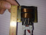
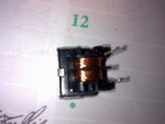
Try to find any broken SMPS, check for a small choke input. You need the small ferrite ring. Most of the coil filter are ready to use. To make the transformer you need 2 separately wound coils, for a estimated 20-30 number of turns of wire in each coil, like in the attached pictures.
 
  • Like
Reactions: cntntn

    cntntn

    Points: 2
    Helpful Answer Positive Rating
I've foud these,
That one is bigger and I think can't work...
Foto347.jpg

I think this is better (it's about 1 cm)
Foto351.jpg

what you think about ?
 

It doesn't work... and killed my arduino :-( ... it doesn't matter :smile:, I'll buy another one
But I think we need to change the circuit...
Have you any idea?
 

can someone help me?
 

There are many issues to consider when dealing high voltage pulses. Making high-voltage measurements can be hazardous to the equipment, and the initial setup was designed to protect the controller input by using limiting diodes.
Later you have discovered problems using the serial interface (this can create a path for high-voltage pulses to the external equipment grounding) and in order to eliminate such noise we should provide an insulation barrier by using isolated measurement devices between the equipment and hazardous voltages. Electrical isolation pertains to eliminating ground paths between two electrical systems by breaking ground loops which are the most common source of noise in data acquisition applications.
There are three basic types of isolation that can be used in a data acquisition system:
-Electromagnetic isolation (uses a transformer to couple a signal across an isolation barrier )
-Optical Isolation (opto-couplers)
-Capacitive Isolation (Capacitive coupling )
We have chosen the electromagnetic isolation by using a separation transformer because that it is very simple to implement, yet practical application requires more attention to the correct execution of all connections.
A good pulse transformer should minimize parasitic capacitive coupling, so it needs to use separated coils with low number of turns (as I have presented in the previous attached pictures).
Not to repeat the same mistakes we should first need to know where and how have you connected the wires. It is critical that this ground wire connection is properly done to the chassis, and it should be as short as possible. Maybe it will be necessary a weak coupling between the induction coil and the measuring probe, so this time try lowering the number of turns up to the limit of capture the necessary pulses.
 

Status
Not open for further replies.

Similar threads

Part and Inventory Search

Welcome to EDABoard.com

Sponsor

Back
Top