Continue to Site

Welcome to EDAboard.com

Welcome to our site! EDAboard.com is an international Electronics Discussion Forum focused on EDA software, circuits, schematics, books, theory, papers, asic, pld, 8051, DSP, Network, RF, Analog Design, PCB, Service Manuals... and a whole lot more! To participate you need to register. Registration is free. Click here to register now.

[SOLVED] 2N2222 transistor basic circuit design ......

Status
Not open for further replies.

kdg007

Full Member level 3
Full Member level 3
Joined
Jan 6, 2012
Messages
162
Helped
1
Reputation
2
Reaction score
1
Trophy points
1,298
Activity points
2,420
Hi ,
I am pretty new to electronics. I am trying to build a basic circuit with 2N2222 transistor.
5VDC supply(+ve) to base and collector pins.
R1 -390 ohms to base,
R2-45ohms and LED(white) connected to the collector side,
R3= 1k ohms connected to the base and emitter and ground.
5VDC (-ve) ground.

when i switched on the battery (5volts)... the LED is not switched on .. according to my calculations,77ma of current must go through the LED.
base current = 10.02ma,collector current = 77.12ma.

-

where did i went wrong ?? any suggestions are welcome :)


thanks in advance !!!!
 

Your description of how R3 is connected isn't clear. Can you explain further?

How did you arrive at the figures for Ib and Ic?
 
Last edited:

What is your desired bias point for the LED? Most of them run about 3.5V and 20 mA. If you really are getting 77mA through the LED, then it probably burned out when you connected 5V to your circuit.

Here's the process I'd start from, for building up your desired switching circuit.

To properly size the current-limiting resistor for the LED (R2), you should assume that the 2N2222 is in saturation. That means that Vce = 0.2V. If the LED needs 3.5V, then you have 5V - 0.2V - 3.5V = 1.3V drop across R2. If you limit the current through the LED to 15mA (which should turn it on, but not be close to burn-out), then R2 = 1.3V/15mA = 87 ohms.

To get the transistor to turn on, you need to pull Vbe to around 0.8V to really turn the 2n2222 on hard. If Ic = 15mA, and the 2N2222 has a low beta, say 75... then Ib need to be at least 15mA / 75 = 0.2 mA. Your voltage divider on the base needs to have a bias current ~20 times that, so that the base current doesn't impact the voltage divider's set-point. The divider current will need to be drawing around... 0.2mA * 20 = 4mA.

5V / 4mA = Rtotal = 1250 ohms (R1+R3)
Using the standard voltage divider equation:
\[Vout = Vin*\frac{R2}{R1+R2}\] ----> \[0.8 = 5*\frac{R2}{1250}\]
We find R2 = 200 ohms
Then R1 = 1250 - 200 = 1050 ohms. Pick standard resistor values close to those (maybe 220 ohms and 1k), and recalculate the divider output voltage, that will become Vbe.

I'd recommend you put your circuit into a simulator like SPICE, ADS or MWO before you jump into building it, so prove out your mathematics (which are horrendously skewed.... Ib = 10 mA is not realistic). Additionally, try your circuit with just resistors (increase R2 so that it drops 4.8V @ 15mA, then it can stand in for your LED and you won't risk blowing it up). Then you can measure the voltage across your resistors and determine the current through most of the legs of your circuit, and see if your math is close to correct.

Some of the numbers in my analysis may not be completely correct, so you will have to experiment with the bais currents and set-point voltages to find the optimum operating condition (review saturation for an NPN BJT to give you some clues on the proper values).
 

Thank you for the brief explanation :) i have pspice .... will try in that first :)
 

bc547.jpg


sadly i couldn't find 2N2222 in pspice but i used similar one BC547a ... These are my results...

Ib is pretty low :O 714 uA... also i am getting 40ma to LED :O :O did i do anything wrong :(
 

View attachment 66856
sadly i couldn't find 2N2222 in pspice but i used similar one BC547a ... These are my results...

Ib is pretty low :O 714 uA... also i am getting 40ma to LED :O :O did i do anything wrong :(

Take another look at your circuit model. The voltages around your diode are 1.460V and 0.1663V, which means the diode is only dropping 1.46-0.1663 = 1.3V, not 3.5V. I think you made the text label say "3.5", but that doesn't change how the diode works... it's still a diode. What you should do is replace the diode with a 3.5V DC source. That should let the simulator do what it needs to do, and will "drop" 3.5V across that component. When you run it again, verify that the voltages around the 3.5V drop add up to ~3.5V.
 

kdg007 said:
did i do anything wrong :(

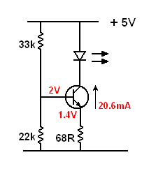
Yes. The current through the transistor is totally undefined.

You need to fix a voltage at the base, then, knowing that the emitter voltage will be 0.6 less than the base, establish the desired current through the transistor by selecting a suitable value for an emitter resistor.

The example below shows what I mean.

leddriver.gif
 

Thank you for the replies :) i will look into it.. think i should read the transistor properties again just to get a clear idea :)
-
have a great week end !!

cheers
 

Status
Not open for further replies.

Similar threads

Part and Inventory Search

Welcome to EDABoard.com

Sponsor

Back
Top