Continue to Site

Welcome to EDAboard.com

Welcome to our site! EDAboard.com is an international Electronics Discussion Forum focused on EDA software, circuits, schematics, books, theory, papers, asic, pld, 8051, DSP, Network, RF, Analog Design, PCB, Service Manuals... and a whole lot more! To participate you need to register. Registration is free. Click here to register now.

Variable frequency sinusoidal wave oscillator

Status
Not open for further replies.

goldsmith

Advanced Member level 6
Joined
Dec 14, 2010
Messages
3,981
Helped
741
Reputation
1,486
Reaction score
726
Trophy points
1,413
Location
Tehran - IRAN
Visit site
Activity points
24,546
Hi My friends
I want to design a sine wave generator with variable frequency ( and agreeable amplitude about
-+15volt) .
and variable frequency from 0.1HZ up to 2MHZ . what should i do?
Is it possible that you guide me please?
All the best
Goldsmith
 

Hi Goldsmith,
I am afraid, there will be no guidance for such a huge design goal (sinusoidal, constant amplitude, tunable over 7 decades).
I suppose, such a device can only be the result of a industrial design & development activity.
Perhaps you should try to get access to a commercial waveform generator circuit diagram?
 

Dear LvW
Hi
Thank your for your reply and attention.
I used the variable oscillator with not gate , ( square wave ) and then i used a comparator to obtain , simultaneous square wave ( +-vcc) . and then i used an integrator circuit , ( with switch for selecting some RC networks of that integrator for variable frequencies) . thus i have a triangle wave and square wave with variable frequency. ( up to 2MHZ) but when i tried to use some methods to obtain sine wave , from triangle wave or square wave , directly , i loosed . i tried some methods to obtain that but all of them had some problem. and i thought that i can create independent sine wave generator.but as you said , it is not possible. what should i do for this aim?
Is it possible that you guide me please?
Yours sincerely
Goldsmith
 

Hi Goldsmith,

up to now, nobody else in the forum gave you some guidance or help. Therefore, I'll make some general statements related to sinusoidal oscillator design (tunable).
For my opinion, there are in general three basic options:
1) Squarewave generation with succeeding active lowpass filtering;
2) Squarewave generation with succeeding integration (triangle generation) and sinusoidal shaping (differential amplifier). Good approach: Triangle generation based on relaxation principle (two opamps);
3) Direct sinus generation with a linear harmonic oscillator.
___________________

The required tuning capabilities are a problem:
For option (1) the filter must be tuned simultaneously with Q factor and filter gain remaining constant.
For option (3) the problem is to find an oscillator circuit with single-element tuning capability over a large tuning range (without disturbing the oscillation condition).
Thus, option (2) could be a solution. However, I doubt if the frequency can be tuned over 7 decades (as mentioned by you).
 
Dear LvW
Hi
Thanks for your really helpful guide.
But about the relaxation method: i tried that circuit , but its frequency could not exceed from some KHZ with LM118( high frequency op amp) and at high frequencies its triangle wave , went to be a sine wave.
What is the problem of that circuit in your idea? and how can i improve that?
Thank you for your guidance
Sincerely
Goldsmith
 

Dear LvW
Hi
Thanks for your really helpful guide.
But about the relaxation method: i tried that circuit , but its frequency could not exceed from some KHZ with LM118( high frequency op amp) and at high frequencies its triangle wave , went to be a sine wave.....

In order to avoid misunderstandings show us the circuit (because there are more than only one).
 

Dear LvW
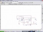
Here is the circuit: triangle generator.JPG
Its action at low frequencies is very well , but at high frequencies , its action will not ok.
Best Regards
Goldsmith
 

I think your mean by relaxation is that circuit. or probably not.

Yes, that's the classical 2-opamp relaxation circuit.
By talking about "low frequencies" (works good) and "high frequencies" (works badly) - what is the usable frequency range (numbers!)?
How did you tune the frequency?
 

    V

    Points: 2
    Helpful Answer Positive Rating
What about building the sine as a the product of two LC oscillators?
For example a fixed one at 20MHz and a 20-22MHz tuneable one.
Then you mix the outputs through a non-linear block - ideally a multiplier - and low-pass filter...

... OK, maybe this is more a joke then a good design suggestion :)
 

Perhaps you should use a waveform generator such as MAX038

As far as I could understand Goldsmith, he wants to DESIGN an oscillatory circuit.
 

    V

    Points: 2
    Helpful Answer Positive Rating
I wonder, if there are additional specifications besides frequency range and voltage range. Strictly spoken, the latter isn't a matter of oscillator design rather than using a reasonable amplifier. For the oscillator itself, you'll need to think about waveform quality respectively distortion, frequency accuracy, amplitude constancy, method of frequency programming, required frequency variation speed (if external programming is intended at all).

You should have at least an idea about these parameters. For basic requirements, a classical triangle generator + sine waveshaper approach, as suggested by LvW, seems reasonable in my opinion, or has been at least the usual method in the past. I previously posted the manual, including schematics of a simple commercial instrument. https://www.edaboard.com/threads/76942/

I should add, that since about 5 or 10 years, (nearly) all newly designed commercial function generators are based on digital signal processing. For the same reason, function generator ICs like MAX038 got obsolete, some similar types like XR2206 are still manufactured.
 
  • Like
Reactions: LvW

    V

    Points: 2
    Helpful Answer Positive Rating

    LvW

    Points: 2
    Helpful Answer Positive Rating
I would recommend a table-DAC approach, and a counter to index
the table, and drive the whole mess with a PLL w/ reference clock.
Though you could also cobble up a /N up counter, that might lack
the granularity of a decent modern PLL. A cheap EPROM and Willem
programmer for the table, 27Cxxx EPROMs can run to about 10MHz
(a fuse PROM, probably higher but these are harder to find these
days).

Your distortion would be in the 1LSB range and filtering at ~fclk/16
corner ought to clean that up.

I've used the EPROM, DAC, 74ACxx counter scheme to make I/Q
modulator test waveforms at 10MHz clock (squared from the signal
generator). That's not going to satisfy your 2MHz wish at any
decent N.

Now you might decide to just forego the amusement and buy
an old Wavetek function generator off eBay for dirt cheap.
You'd have to supply the amplifier to get +/-15V, but it's
going to have the purity and range you want (with an old-
timey dial, no digital).

I think you'll want to decompose the problem into VCO
(small signal, for purity and simplicity) and an AGC gain
block (for fixed output independent of frequency) if you
are after the experience of designing it and not just
looking for a signal source to do a job.

Now there are also switched capacitor filters which
can chop all the harmonics off a square wave real nicely.
Generate the 256X (or whatever) with your VCO, divide
it down for the fundamental and run that fundamental
through the N-pole filter and you've got the sine wave.
Still need the AGC/gain block for your desired amplitude.
 

    V

    Points: 2
    Helpful Answer Positive Rating
If my memory doesn't fail, there was an ooold application note of the LM13600 OTA showing tunable filters and variable frequency oscillators spanning several decades.

Of course, nowadays digital techniques are preferred.

There were heterodyne generators working as per Dave9000 suggestion. Problem is stability, mainly when generating lower frequencies.
In electronic music, that is the idea behind the Theremin.

Regards

Z
 

    V

    Points: 2
    Helpful Answer Positive Rating
Dear all
Hi
Thanks for all of your answers.
for changing the frequency i used this web site to design:**broken link removed**
and , i don't want to use DSP or digital systems for this aim , and i want to design it with analog circuits ( but for square wave , i can use from gates .)
and about xr2206 : its frequency is not pretty stable and it changes about some hertz ant low frequencies .and about some kilo hertz at high frequencies.

and dear , dick_freebird
Is it possible that you more describe your offered way , please?
And Dear friends
Is it possible that you guide me , please?
Can i improve attached circuit to obtain my desired frequency?
I can remember , that , when i was in vocation , some of our function generators was analog , and some of one was Digital . but analogs are better , in my idea , because i working on high voltage circuits , and it is possible , that my function generator , become destroy. and if that , be analog , i can repair it simply. until know some of my function generators are destroyed , with high voltage reflection!
Thanks my friends
Best Regards
Goldsmith
 

and about xr2206 : its frequency is not pretty stable and it changes about some hertz ant low frequencies .and about some kilo hertz at high frequencies.
I take this as hint, that you actually have specification in mind. It would helpful, if you can communicate it.

but analogs are better , in my idea , because i working on high voltage circuits , and it is possible , that my function generator , become destroy. and if that , be analog , i can repair it simply. until know some of my function generators are destroyed , with high voltage reflection!

Once again, this is a matter of output amplifiers, not the generator itself. (As long as you aren't imaging something like a single stage vacuum tube generator...).

i don't want to use DSP or digital systems for this aim
I have no problem to accept this. However, are you aware of the implications? It's effectively impossible to have seven decades frequency control and high frequency stability at the same time. The linked Purdue project report e.g. is using a potentiometer for frequency control. It can work over 2 or 3 decades with an accuracy reasonable e.g. for an audio test generator. You'll need switches or relays to change capacitors for a wider range. VCOs based on OTAs, electronically variable resistors or similar means can achieve a wider range under some conditions. But for stable and accurate frequency control, you'll possibly need a PLL, which would cross the border to digital systems.
 
Dear FvM
Hi again
Thank you for your guidance . for selecting the capacitors , i can use from switches as well as. but how can i design or use a high frequency VCO and PLL at this circuit? and is your mean that , the attached circuit is not good for this purpose? if yes , why , and how can i solve this problem?
is it possible , that you guide me , please?
Kind Regards
Goldsmith
 

Very clearly, the circuit is limited to manual frequency programming by variable resistor. VCO in my post doesn't mean a particular circuit technology, just an oscillator with electronical frequency control. OTA based oscillators have been mentioned as an example.

It's however not clear to me, what you're exactly intending. I referred to the FG1617 function generator, which is just one of many pure analog generators which are still available on the market, e.g. this one https://www.farnell.com/datasheets/42616.pdf

The mostly have decadic frequency switches and a continuous control over one decade. A triangle generator like the shown one can easily be controlled like this, with sufficient fast OPs, 2 MHz isn't an issue.
 

Dear FvM
"It's however not clear to me, what you're exactly intending"
I want design a function generator.
I design a simple variable frequency square wave oscillator with some HF note gates . and i can obtain a triangle wave from that . but at frequencies more than 1.3MHZ i can not use my integrator , because the out put shape will destroy . and i think that my op amp can not work at that frequencies ( its harmonics ) . i used LM118 . what should i do ? ( i changed the value of capacitor of miller integrator for that, by variation at frequency ).
Appreciate
Goldsmith
 

Status
Not open for further replies.

Part and Inventory Search

Welcome to EDABoard.com

Sponsor

Back
Top