Continue to Site

Welcome to EDAboard.com

Welcome to our site! EDAboard.com is an international Electronics Discussion Forum focused on EDA software, circuits, schematics, books, theory, papers, asic, pld, 8051, DSP, Network, RF, Analog Design, PCB, Service Manuals... and a whole lot more! To participate you need to register. Registration is free. Click here to register now.

How to calculate the Half wave rectifier capacitor value

Status
Not open for further replies.

Bjtpower

Full Member level 5
Joined
Dec 24, 2015
Messages
297
Helped
2
Reputation
4
Reaction score
2
Trophy points
1,298
Activity points
3,893
I am trying to make the procedure for the Half wave rectifier Design.

Over which i am confusing on the calculation of capacitor value..??

Can anyone let me know how i can calculate the same..?

Marx
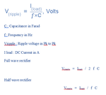
 

There is no prompt formula for capacitor calculation.People will prefer to fix the value of capacitor practically with help of CRO.
I can say that the capacitance value should be bauble in half bridge compared to full bridge rectifier because more ripple will appears in half bridge. Ripple.png
 
You can easily derive that the given formula is an exact solution for small current flow angle. In any case it's a maximum limit for ripple voltage. Actual value can be less with relevant transformer R and X percent or small capacitor.
 
Thank you..

Does it have any relationship with the
I=C(dV/dT)..??

I understand that the it is equivalent to Full wave bridge DC output if the Capacitor value is too High.

Regards
Marx

- - - Updated - - -

Then what is the Average value in case of Capacitive Filter

I read somewhere vdc=0.45Vpeak..
 

Hi,

The calculation is relatively simple.
1F = 1 As / V, or C = I x t / V.

It says: you need 1F for a load current of 1A for 1second of time and a voltage (drop) of 1V

Example:
You have a frequency of 50Hz, 0.1A of load current and you want the ripple(peak-peak) to be about 2V.
50Hz gives 20ms for a half wave rectifier (period time = max discharge time)
Then C = I x t / V = 0.1A x 0.02s / 2V = 0.001F = 1mF = 1000uF.
( C = capacitance in F, I = average load current in A, t = discharge time in s, V is voltage ripple (pp) in V)

With this formula you are on the safe side, because discharge_time is less than 20ms.
20ms = mains_frequency_period_time = charge_time + discharge_time

Klaus
 
Does it have any relationship with the I=C(dV/dT)..??
Surely, just consider the output capacitor instantly charged during the input voltage peak and discharged in a sawtooth waveform.

I understand that the it is equivalent to Full wave bridge DC output if the Capacitor value is too High.
Why too high? A relative large filter capacitor is the usual case if a half wave rectifier is used in a DC power supply.

Then what is the Average value in case of Capacitive Filter

I read somewhere vdc=0.45Vpeak..
A rectifier with filter capacitor is a non-linear circuit, the output voltage average depends on load current and capacitor value and can't be described by a constant value.

Putting a linear averaging filter after a rectifier would be an approach for a measurement circuit (to derive average rectified value of an AC voltage), not a power supply. You need to guarantee that charging and discharging time constants are equal, discharged not blocked by the rectifier.
 
Hello,
Here is a simulation, (LTspice) which you can use to check the ripple voltage, capacitor ripple current, etc etc.
 

Attachments

  • Half Wave Rectifier capacitor.txt
    1,020 bytes · Views: 244
Status
Not open for further replies.

Part and Inventory Search

Welcome to EDABoard.com

Sponsor

Back
Top