Continue to Site

Welcome to EDAboard.com

Welcome to our site! EDAboard.com is an international Electronics Discussion Forum focused on EDA software, circuits, schematics, books, theory, papers, asic, pld, 8051, DSP, Network, RF, Analog Design, PCB, Service Manuals... and a whole lot more! To participate you need to register. Registration is free. Click here to register now.

Dual Complementary Rectifier PSU Calculation

VirusX2

Member level 4
Joined
Nov 18, 2014
Messages
77
Helped
1
Reputation
2
Reaction score
0
Trophy points
1,286
Activity points
1,849
Hi all,

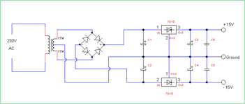
i have an 60VA transformer with 2x15V secondary, rated at 2A each. I want to use it on a dual symmetrical dc power supply with outputs, +15V,-15V.
The circuit is with filtering capacitor and LM7815/LM7915 on each rail.

Except of the dual supply loads such as op-amps and transducers, i have some single-ended loads from +15V to common 0V and from -15V to common 0V.

Lets say i need 1.3A from +15V to common 0V, 50mA from -15V to common 0V, and 150mA symmetrical load on+15V/-15V

I am a little confused. Can you help me calculate the the total AC RMS current needed from the transformer?
I attached the circuit.

Thank you.
 

Attachments

  • 15-Volt-dual-power-supply-circuit.png
    15-Volt-dual-power-supply-circuit.png
    10.5 KB · Views: 35
Hi,

if you want to do it pyhsically and mathematically correct you need to know the values of C1, C2 and the impedance charging these Cs (this also includes the ESR of the capacitors)
It´s a lot of math, so better run a simulation.

***
A very inaccurate estimation:

positive side output current is: 1.3A + 0.15A = 1.45A DC
negative side output current is 0.05A + 0.15A = 0.2A DC

the voltage across the bulk capacitors is up to 15V x sqrt(2) (for ideal transformer and ideal mains supply, which is not realistic)
so lets say about 21V (rectifier loss also not included).

No we have about 21V ... and combined of both sides we have an average current of 1.65A.

Now charging of the capacitors (C1, C2) happens oly at the peaks of the sine mains voltage. let´s say twice in a period for maybe just 20% of time.
Again if we (unrealistically) say the current is like a square wave, then the current is 1.65A / 20% for 20% of the time.
So 8.25A for 20% of time.

For square wave currents: the RMS current is the peak current * sqrt(duty cycle), so 8.25A x sqrt(20%) = 8.25A X 0.5 = 4.125A RMS (combined for both sides)

Each output is rated with 2A RMS, making a total of 4A RMS.

--> with the given load the transformer is yet a bit overloaded.

While the load (output) power is just 1.65A x 15V = 24.75W
The transformer average output power may be about 35W (The difference of about 10W is dissipated in diodes and voltage regulators as heat)
But the apparent transformer output power is about 60VA due to power factor.

Klaus
 
Thanks a lot!

I don't want to calculate the currents strictly mathematically, but i want to go with some “design” equations to be as close enough as i can.

Maybe there are different rations of DC-to-RMS for the single ended loads and the common mode +-15V?
 
Hi,
Maybe there are different rations of DC-to-RMS for the single ended loads and the common mode +-15V?
No. There is no fixed ratio.
The only thing is that the common mode causes current in the negative leg as well as in the positive leg, thus it causes twice as much current in the winding than a single ended current.

And it is about independent of output voltage. If you have the same current on the outputs of 7805 / 7905 = +/-5V the winding current will stay the same.

Why this "old style" power supply at all?It does not make much sense nowadays.

Klaus
 
As explained, exact Irms depend on capacitor values and also transformer impedance (winding resistance and leakage inductance), there are however rules of thumb. Due to the asymmetrical load, the current waveform is near to single wave rectifier. Irms is usually calculated with a form factor of 2.0, but in contrast to single wave rectifier, current is shared between two windings. I get Irms = 1.45*0.5*2.0 = 1.45 A, o.k. with 60 VA transformer. I neglect current into negative path because it contributes only 1% to Irms.
 
I neglect current into negative path because it contributes only 1% to Irms.

you say 1% because you add them with "square" method?
Square method is used when adding two independent RMS values.

But here the currents in the coils are not independent, they happen exactly at the same timing.
Thus one needs to add them quit using "+".

more thinking....

OK. You maybe consider the currents in two different secondary coils, thus the one coil sees 1.45A with it´s power dissipation .. and the other sees 0.15A with it´s power dissipaton. Until here I can agree with the 1%.

But in the primary coil both currents are combined using "+" because they happen at the same time.
So I guess it´s a mixture of both: the average power dissipation of both secondaries is just raised by 1%
But the power dissipation of the primary is raised by about 20%.


Klaus
 
But in the primary coil both currents are combined using "+" because they happen at the same time.
So I guess it´s a mixture of both: the average power dissipation of both secondaries is just raised by 1%
But the power dissipation of the primary is raised by about 20%.
I agree. But primary winding carries symmetrical current and isn't affected by single wave form factor. Secondary winding is the bottleneck in this application.
 
total AC RMS current needed from the transformer?
The running amount is one item yet as Klaus points out (post #2) current is admitted as brief strong bursts at each voltage peak. Following your schematic I made a simulation. I adjusted values to result in providing +12V -12V. Current draw approximates your spec loads. Each burst is over 6 Amperes briefly using ideal components. The center-tap itself has lesser bursts.

Notice the twin secondaries contribute no differently from each other even though they conduct at different halves of a cycle. This is because both their current outputs goes through the full-diode-bridge as is shown by the Ammeter on the topmost wire (arrowhead icon).

power supply conventional xfmr ctr-tap 15-0-15 dio-bri caps loads.png
 
For large output caps the power factor of the ckt is typically 0.6 or a wee bit less

So - for -15 / 0 / + 15 out at 1A say - the total power would be 30 watts out required, divide by 0.6 = 50VA requirement for the transformer

so 1.7 A rms per output wdg, and 230Vac in wdg needs to tolerate 220mA

these results can be scaled to any situation.
 
So - for -15 / 0 / + 15 out at 1A say - the total power would be 30 watts out required, divide by 0.6 = 50VA requirement for the transformer
No.
Just imagine it used 7805 and 7905 to get +/-5V output voltage. Then the output power at 1A current was just 10W.
But indeed it would not change secondary nor primary coil current.

--> When using linear regulators you always need to calculate with the bulk capacitor voltage.

Klaus
 
The discussion is falling behind previous results. The specific question was about asymmetrical load of 15V/1.3A and -15V/0.15A. In this situation we have effectively single wave rectifier current waveform in secondary windings and need more transformer power margin.

As previously calculated, planned 60 VA transformer is well sufficient. OP was asking for exact design equations which isn't so simple.
--- Updated ---

60 VA rated transformer power is o.k., but 15 V is marginal for 7815. Need to consider capacitor ripple voltage and grid voltage variation.
 
Last edited:

LaTeX Commands Quick-Menu:

Similar threads

Part and Inventory Search

Welcome to EDABoard.com

Sponsor

Back
Top