Continue to Site

Welcome to EDAboard.com

Welcome to our site! EDAboard.com is an international Electronics Discussion Forum focused on EDA software, circuits, schematics, books, theory, papers, asic, pld, 8051, DSP, Network, RF, Analog Design, PCB, Service Manuals... and a whole lot more! To participate you need to register. Registration is free. Click here to register now.

analog intuition regarding regulating circuit

yefj

Advanced Member level 4
Joined
Sep 12, 2019
Messages
1,234
Helped
1
Reputation
2
Reaction score
3
Trophy points
38
Activity points
7,410
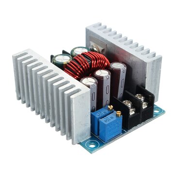
Hello ,I have ere this very intresting circuit which transforms 24V into 20V.
it could be dont using simple voltage divider :) .
Could you help me with intuition regarding how this circuit works so i could learn its functionality and tune it?
Thanks.

1714322139544.png
 
Neglecting for a moment R2 and R3, we have a zener TL341 connected to
base of NPN. TL431 is biased via R1. So writing a loop equation VZ + Vbe = Vout.

1714322957086.png


But we have a fdbk loop and Vout can be described as a f() of
Vref and Iref x R2 in above. So you can solve for the output.

Of course you "tune" Vout with the ratio of R1/R2 in above pic.

1714324563843.png


Regards, Dana.
 
Last edited:
Could you help me with intuition regarding how this circuit works
The TL431 is a programmable shunt regulator (rather like a programmable Zener).
It starts to conduct current, cathode-to-anode, when the voltage at it REF pin (junction of R2 and R3 in your circuit) goes above 2.5V.
When it conducts, then it sinks current from R1, thus reducing to base current Q1 and reducing its output.
The TL431 thus adjusts the base current so its REF voltage stays at 2.5V with the output at a voltage that generates 2.5V at the R2-R3 junction.
The REF input draws a very low current so doesn't affect the junction voltage.

Make sense?
 
Sorry for the simple question :)
What is the advantage of this structure over a simple voltage divider ?which could transform 24 to 20 also .
Thanks .
 
Hello Dana, My load is 1.5Ohm and i need 20V and 12A threw the load,Also i need to make the regulator switched by input pulse
0-5V 120ns ON 500ns period.Is there a way to change the configuration to do that?
could you reccomend me PNP/MOSFET and Zenner i could use in LTSPICE to make a high current switced voltage regulator from this configuration? :)
 
If you have to drop 4V with 12A running thru it you waste ~50W of power,
and need big heatsink. But if you use switch mode power supply, at ~80%
efficiency, much greener approach, heat sinks much smaller.

This is possibility :


But its not suitable for 2 Mhz switching enable.

Goto digikey, pick a FET from selector table filters, with margin on Vds and Idrain, say 50%.
Now you will have to design gate drive circuit which will be challenging to get 2 Mhz switching
enable......or pick a bipolar for a starting point. When you disable what is Vload max you desire ?

Take a look at : https://www.digikey.com/en/products...uI7kj2RoSG0CCefAogXLyQAsLiUoTcAJ6cuHwe2CjS0kA


Regards, Dana.
 
Last edited:
Also i need to make the regulator switched by input pulse
0-5V 120ns ON 500ns period.
Definitely impossible with this or similar circuits. To follow a pulsed voltage setpoint, the control loop needs a bandwidth of multiple 10MHz, neither TL431 nor audio frequency BJT darlington TIP142 can. Furthermore, other than suggested by the simulation circuit, your load isn't resistive. It involves most likely bypass capacitors necessary for stable operation of the supplied microwave amplifier.

After finally revealing pulse width and period parameters of your project, can you give an idea about the intended rise and fall time?
 
Hello Dana,When i disable that regulator it would be good to have as slow as possible :)
So is there some analog logic i could follow to implement it?


Hello FVM, rise and fall time are 3ns.
Thanks.
 
Last edited:
Hello Dana, My load is 1.5Ohm and i need 20V and 12A threw the load,Also i need to make the regulator switched by input pulse
0-5V 120ns ON 500ns period.Is there a way to change the configuration to do that?
could you reccomend me PNP/MOSFET and Zenner i could use in LTSPICE to make a high current switced voltage regulator from this configuration? :)
If you have 20 V across a 1.5 ohm load, then 13.3333+ A flowing through it. If you need 12 A through it, then you need to put 18 V across it.
 

LaTeX Commands Quick-Menu:

Similar threads

Part and Inventory Search

Welcome to EDABoard.com

Sponsor

Back
Top