Electrical Ground is the reference point in circuits from which voltages are measured. Using the symbol of ground we can make our circuits looks simpler. Three types of electrical grounds are:
Simple ground
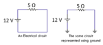
This type serves as simple reference point from which we designate all components. The left side of image below contains 12 V battery in series with a resistor. The right side displays same circuit with ground.

Digital Ground
This ground is often used in digital electronics with components such as Logic gates and flip-flop IC's. Symbolically it is a triangle. The image below displays AND gate which is digitally grounded.

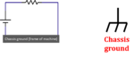
Chassis ground
Sometimes the chassis of metal is used a reference point. For example the metallic base of pc can be connected with circuit's ground and can be used as chassis ground.

Earth ground
The electrical machines and power components to the earth (earth soil) via means of a conductive rod, which is driven in to ground. An earth protects the connected equipment from electrocution. In case of over-current faults it redirects the faults to earth ground.
- Simple ground
- Digital Ground
- Chassis ground
- Earth ground
Simple ground
This type serves as simple reference point from which we designate all components. The left side of image below contains 12 V battery in series with a resistor. The right side displays same circuit with ground.
Digital Ground
This ground is often used in digital electronics with components such as Logic gates and flip-flop IC's. Symbolically it is a triangle. The image below displays AND gate which is digitally grounded.
Chassis ground
Sometimes the chassis of metal is used a reference point. For example the metallic base of pc can be connected with circuit's ground and can be used as chassis ground.
Earth ground
The electrical machines and power components to the earth (earth soil) via means of a conductive rod, which is driven in to ground. An earth protects the connected equipment from electrocution. In case of over-current faults it redirects the faults to earth ground.