noobeestudent
Member level 1

- Joined
- Jul 4, 2019
- Messages
- 37
- Helped
- 0
- Reputation
- 0
- Reaction score
- 0
- Trophy points
- 6
- Activity points
- 290
Hey, I need help with my assignment. I was required too build a Phase Firing Circuit for a aquarium heater that I am going to use in a PCB Etching Tank.
I've finalized the design for the Phase Firing Circuit and now I need help in designing the Zero Crossing Circuit.
For the Zero Crossing Circuit, I am using a 4n25 Optocoupler to detect the zero crossing point.

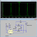
This is my initial design. The green trace represents the AC while the blue trace is the voltage measured across the resistor R1.
Although simulation is working, it seems that the 4N25 should not be able to support the voltage supplied.
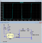
Thus, I have added a current limiting resistor of value 1MΩ after the bridge rectifier. However, doing that decreases the voltage of the resistor R1.
This might caused a few errors as my PIC might not be able to detect it.

From the simulation, the voltage drop across R1 is observed to drop significantly.
I am currently stuck and not sure what I should do to overcome this problem. Please help and provide suggestions.
Below attached is the simulation circuit file.
I've finalized the design for the Phase Firing Circuit and now I need help in designing the Zero Crossing Circuit.
For the Zero Crossing Circuit, I am using a 4n25 Optocoupler to detect the zero crossing point.
This is my initial design. The green trace represents the AC while the blue trace is the voltage measured across the resistor R1.
Although simulation is working, it seems that the 4N25 should not be able to support the voltage supplied.
Thus, I have added a current limiting resistor of value 1MΩ after the bridge rectifier. However, doing that decreases the voltage of the resistor R1.
This might caused a few errors as my PIC might not be able to detect it.
From the simulation, the voltage drop across R1 is observed to drop significantly.
I am currently stuck and not sure what I should do to overcome this problem. Please help and provide suggestions.
Below attached is the simulation circuit file.


