Continue to Site

Welcome to EDAboard.com

Welcome to our site! EDAboard.com is an international Electronics Discussion Forum focused on EDA software, circuits, schematics, books, theory, papers, asic, pld, 8051, DSP, Network, RF, Analog Design, PCB, Service Manuals... and a whole lot more! To participate you need to register. Registration is free. Click here to register now.

Zener voltage regulator problem

Status
Not open for further replies.

In2Dusk

Junior Member level 3
Joined
Jul 9, 2011
Messages
31
Helped
0
Reputation
0
Reaction score
0
Trophy points
1,286
Activity points
1,496
I have PIC18F45K20 which idealy needs 3.3V and i need to power it by 4x 1.5V alkaline battery that's 6V input voltage.
I used zener voltage regulator as shown here:
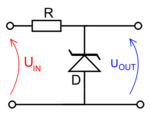
390px-Zener_diode_voltage_regulator_svg.png
Vz = 3.3V and I used 25 Ohm resistor in serie with diode.
And i get output voltage of 4.3V!!!
How is it possible? Did i make a mstake somewhere?
 

As you said,output voltage is 4.3V, the voltage drop on R is 6-4.3 = 1.7V, the current through R is 1.7V/25=68mA;

the zener in breakdown condition, the voltage will be 3.3V, current will more bigger than 68mA;

It's not a better choice for you to get 3.3V voltage in such way; you may choice a DCDC to convert 6V to 3.3V;
Hope help for you.
 
Last edited:

the voltage drop on R is 6-4.3 = 2.7V, the current through R is 2.7V/25=108mA;
broken pocket calculator?

However, although 68 mA may be above the current specfied with nominal zener voltage of 3.3 V. You have to review the datasheet, manufacturers are using quite different values.

I think, it's a bad idea to use a zener regulator with batteries, beacuse it considerably reduces their lifetime. An integrated 3.3V voltage regulator would be much better, consuming only a small quiescent current and the current actually required by the load. For highest efficiency, a switch mode converter will be recommended, but I guess, it's not reasonable in your case.

What's the 3.3V load current?
 
I have correct misktake in previous post.

by the way , though we could get 3.3V voltage, almost the power has lost in zener diode. so it's a bad choice to get voltage for MCU from zener.
 

It's even worse, you don't just lose the voltage, but also additional current to operate the zener regulator. But I think that a linear regulator will be appropriate for most designs with moderate current demand, e.g. up to 50 mA. A switch mode supply can however raise the efficiency from 55% to 80-95%, depending on the switcher perfomance.
 

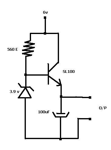
If there is no much loading in the O/P , then i think this circuit could be used.

0_1310210373.jpg
 
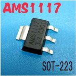
Why reinvent the wheel, a simple regulator like LM1117 will have better regulation, takes less space and as a bonus you get current limiting and thermal protection
**broken link removed**

AMS117_1.jpg

Alex
 
A simple switcher would be more efficient and give longer useable time from your batteries, Regards, Orson Cart.
 

Status
Not open for further replies.

Similar threads

Part and Inventory Search

Welcome to EDABoard.com

Sponsor

Back
Top