Continue to Site

Welcome to EDAboard.com

Welcome to our site! EDAboard.com is an international Electronics Discussion Forum focused on EDA software, circuits, schematics, books, theory, papers, asic, pld, 8051, DSP, Network, RF, Analog Design, PCB, Service Manuals... and a whole lot more! To participate you need to register. Registration is free. Click here to register now.

Wrong result of Rds(on) from simulation model of NMOS

Status
Not open for further replies.

Lucast85

Member level 3
Member level 3
Joined
Oct 19, 2009
Messages
62
Helped
4
Reputation
8
Reaction score
4
Trophy points
1,288
Location
Italy
Activity points
1,966
Hi everyone,
I've tryed to simulate some Infineon Mosfets by using differents models they provide on the website.
I'm interesed into RDS(on) value and into self-heating behaviour. During simulation I cannot reach the Rds(on) as declared on the datasheet. However by trying different Mosfets from other manufacturer I can measure the declared Rds(on) with the same test circuit.
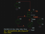
This is the circuit setup by using LTspice and IPB015N08N5 NMOS:
RDS_mos.png
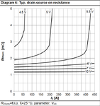
As you can see the Vgs is a pulse of 10V, the drain current is 100A (dissipative Isource, or load), and the case temperature is forced to be 25°C. The datasheet report a typical RDS(on) of 1.1 mohm but the simulation give me an RDS(on) of 2.15mohm (calculated as Vds/I1) when MOS is on.
RDS_mos_datasheet.png
Why? Any idea?
 

Hi everyone,
I've tryed to simulate some Infineon Mosfets by using differents models they provide on the website.
I'm interesed into RDS(on) value and into self-heating behaviour. During simulation I cannot reach the Rds(on) as declared on the datasheet. However by trying different Mosfets from other manufacturer I can measure the declared Rds(on) with the same test circuit.
This is the circuit setup by using LTspice and IPB015N08N5 NMOS:
View attachment 150640
As you can see the Vgs is a pulse of 10V, the drain current is 100A (dissipative Isource, or load), and the case temperature is forced to be 25°C. The datasheet report a typical RDS(on) of 1.1 mohm but the simulation give me an RDS(on) of 2.15mohm (calculated as Vds/I1) when MOS is on.
View attachment 150642
Why? Any idea?
you say 1.1 is TYPICAL value. Maybe the model is simulating worst case? Also, why are you configuring this as a source follower? Maybe try putting the load in the drain.
 

Reading from the datasheet I see the max Rds(on) when Id=100 A and Vgs=10 V is 1.5 mohm. I think this is the worst case instead I measure 2.15 mohm. I use the source follower configuration because this will be the final application but nothing has changed by putting the load in the drain.

I notice the following parameters in the NMOS subcircuit model:
".PARAM Rs=656u Rg=1.5 Rd=50u Rm=163u"
Analyzing the mosfet structure utilized by Infineon (https://www.infineon.com/dgdl/Spice%20Models.pdf?fileId=db3a30431441fb5d01147319b2800b06) maybe I've to add to the Rds(on) read from the datasheet the resistances of the bond wires of the package Rs and Rd (that are 0.65 mohm and 0.05 mohm). So the maximum expected Rds(on) is 1.5 + 0.65 + 0.05 = 2.2 mohm. Anyway I think the Rds(on) in the datasheet already take into account for the wires bond resistances so this could not be the solution.

MOS_model_Infineon.png
 

I'm not an expert on spice models, but I still question why you would use a follower configuration rather than putting the load in the drain (or using a P-channel device).
 

Apparently the model doesn't represent Rdson correctly. Complain at Infineon.

Your simulation circuit drives the MOSFET into avalanche breakdown, needs a clamp diode for current source. But it gives still 2.15 mOhm Rdson after correction.
 

One question is the parameterization of the FET model and
the compatibility between simulators (LTSpice now, OK; but
what is the source platform that "should give" the right
answer? Like, I have seen some SPICEs that don't want
W, L at all (meant for discrete FETs, not parametric
geometries like in IC design), there's the MKS vs CGS units
problem, there's whether things like thr S/D resistance and
overlap capacitances are fixed or W-parametric and so on.

So first question is, is the FET model you picked from a
source that says it's LTSpice compatible?

Another question is, was your Rds(on) testbench identical
in topology and values, to what Infineon shows for conditions?
Some of the chatter above, suggests not. Apples:apples,
when in doubt.
 

The Infineon library is designed for PSpice, as far as I see it's essentially using analog behavioral modelling rather than specific MOSFET models. I guess the results are the same under PSpice.
 

Perhaps, but LTSpice has kind of gone its own road behavioral-
model-wise, have seen some discussions about "B sources" and
various incompatibilities... I'd want to see a PSPice engine, PSpice
model, correct circuit topology simulation result as a baseline.
 

Status
Not open for further replies.

Part and Inventory Search

Welcome to EDABoard.com

Sponsor

Back
Top