fiflakpl
Newbie level 3

Howdy,
My name is Filip and I am currently working on my capstone project which is a design of a wireless charger. I was assigned to work on the computer simulation using ANSYS HFSS. Unfortunately I am not familiar with the software at all and despite hours I spent trying to figure out a lot of things, I didn't succeed. As the result I decided to create a thread where I could ask questions and hopefully get some suggestions on each stage of my work.
As of right now, I am comfortable with creating different shapes of 3D models and have some idea about analysis set up etc.
I decided to solve my problem by splitting it into few smaller stages (since simulating the final design will take forever, I want to make sure everything is set up properly instead of wasting few hours at the time).
1st stage- creating a singular helical coil and calculating its inductance as well as observing how radius change influences inductance value.
I was able to made a 3D model of mentioned coil, however I don't know how to apply excitation to my structure?
I tried applying lumped port on both sides of the polygon helix, but it doesn't work. "All the faces selected from a port source must lie on the same plane. What would be y'alls suggestion?
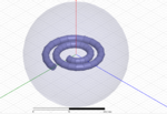
PS. I am using HFSS 15.0 and that's the simple design I started with:

Regards,
FiflakPL
My name is Filip and I am currently working on my capstone project which is a design of a wireless charger. I was assigned to work on the computer simulation using ANSYS HFSS. Unfortunately I am not familiar with the software at all and despite hours I spent trying to figure out a lot of things, I didn't succeed. As the result I decided to create a thread where I could ask questions and hopefully get some suggestions on each stage of my work.
As of right now, I am comfortable with creating different shapes of 3D models and have some idea about analysis set up etc.
I decided to solve my problem by splitting it into few smaller stages (since simulating the final design will take forever, I want to make sure everything is set up properly instead of wasting few hours at the time).
1st stage- creating a singular helical coil and calculating its inductance as well as observing how radius change influences inductance value.
I was able to made a 3D model of mentioned coil, however I don't know how to apply excitation to my structure?
I tried applying lumped port on both sides of the polygon helix, but it doesn't work. "All the faces selected from a port source must lie on the same plane. What would be y'alls suggestion?
PS. I am using HFSS 15.0 and that's the simple design I started with:

Regards,
FiflakPL
Last edited:


