HBRIDGE
Newbie level 2

- Joined
- May 16, 2015
- Messages
- 2
- Helped
- 0
- Reputation
- 0
- Reaction score
- 0
- Trophy points
- 1
- Activity points
- 29
Basically, I'm trying to implement a simple single-phase inverter. I have a sine wave generator, a triangle wave generator and I have created PWM signals out of them using some op-amps and comparators (I haven't yet done a schematic, just a mix of different schematics I've seen online that I've put together to work for me)
I've created the PWM signals, or so I think (tri-level PWM) and before I go connecting this to the MOSFET's I just want to be sure that it's OK, because I have a feeling I'm going to end up short-circuiting the supplies. So if you consider the four H-BRIDGE switches like this:

Whilst S1 is having PWM input to its gate, S4 is ON, then whilst S3 has PWM input to its gate, S2 is ON. The lower switches (S2 and S4) are controlled by a square wave signal, so it's either ON or OFF. Only the upper switches have PWM.
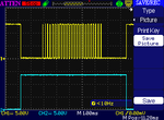
Here is the waveform for the upper left-hand side switch and lower right-hand side switch, CH1 (yellow) is upper and CH2 (blue) is lower, there are sections where there will be short-circuiting (roughly 100us), is this acceptable or have I got this completely wrong? I'm thinking that when S2 is OFF, S1 should also be completely turned off, why would I be getting a PWM signal whilst it's turned off? See below
Here is a zoomed-out version:
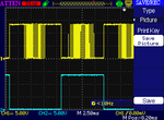
You can see that when S1 is turned on and has PWM, S2 is completely off, that's fine! But when S2 is ON, S1 is off, but it starts having PWM in the middle for a bit.
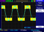
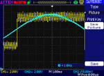
Here is my trilevel PWM, the reference sine wave superimposed on it.
Any advice appreciated, I'm hoping someone can tell me why, I know it's hard without a schematic, but I haven't drawn one out yet.
I've created the PWM signals, or so I think (tri-level PWM) and before I go connecting this to the MOSFET's I just want to be sure that it's OK, because I have a feeling I'm going to end up short-circuiting the supplies. So if you consider the four H-BRIDGE switches like this:

Whilst S1 is having PWM input to its gate, S4 is ON, then whilst S3 has PWM input to its gate, S2 is ON. The lower switches (S2 and S4) are controlled by a square wave signal, so it's either ON or OFF. Only the upper switches have PWM.
Here is the waveform for the upper left-hand side switch and lower right-hand side switch, CH1 (yellow) is upper and CH2 (blue) is lower, there are sections where there will be short-circuiting (roughly 100us), is this acceptable or have I got this completely wrong? I'm thinking that when S2 is OFF, S1 should also be completely turned off, why would I be getting a PWM signal whilst it's turned off? See below

Here is a zoomed-out version:

You can see that when S1 is turned on and has PWM, S2 is completely off, that's fine! But when S2 is ON, S1 is off, but it starts having PWM in the middle for a bit.
Here is my trilevel PWM, the reference sine wave superimposed on it.


Any advice appreciated, I'm hoping someone can tell me why, I know it's hard without a schematic, but I haven't drawn one out yet.
Last edited by a moderator:


