Vermes
Advanced Member level 4

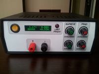
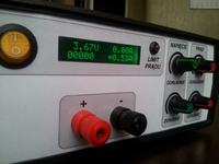
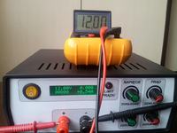
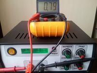
Presented device is a workshop-laboratory power supply with adjustable voltage 0-30V and 0-8A consumed current.
Main assumptions:
- the power supply should be equipped with a multimeter showing current and voltage
- all elements in one housing (Z-17) without protruding heat sinks or fans
- voltage and current regulation provides protection against short circuit and maximum current consumed
- the device is equipped with cooling
- the smallest power loss possible
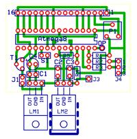
The boards were made in ExpressPCB. There are two main PCBs and multimeter.
The board of the meter has threaded elements without SMD. Software of the meter „load” displays the set current limit, what facilitates work. OP input (at potentiometers) should be connected to Atmega 28 pin on the second board (main power supply board) so the current limit can be displayed.
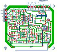
Another PCB is the power supply board. Its dimensions are 80mm x 75mm. Its main advantage is operational amplifiers stabilization, OpAmp uA741. Path powering the collectors of power transistors was disconnected, so power losses can be limited and you can switch transformer's windings. TIP35C were used as the output transistors. Transistor which controls others transistors is TIP32. You can also smoothly set the current limit, instead of resistor there is 100k potentiometer.
Now something about the third PCB. It consists of four modules (transformer's windings switch, fan controller, transformer's soft start system, supply systems with filtering for the 2nd PCB).
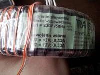
Automatic windings switch is based on a double operational amplifier LM358 working as a comaprator. Voltage of switching relay can be controlled by the potentiometer, in this power supply it is set on 14V. The second section of double amplifier was used to control the fan. Temperature can be controlled by any NPN transistor. The switching temperature can be adjusted using the potentiometer. In its design, the fan turns on at about 60 degrees Celsius. Sensor LM35 was used to test that temperature, you can easily test the temperature range of 1-100 degrees Celsius using that meter. The board is stabilized, powered by 12V from a separate transformer. It has two supply systems: the first one is used for powering the main supply, additionally instead of diodes there is 25A bridge, 10 000uF/50V capacitor. The second system is used for powering OpAmps on the second PCB, it has a separate supply about 28V. Additional windings were applied to the main transformer what provides the limitation of power losses. The main winding of the transformer is 2x12V. Transformer used in the power supply is 2x12V / 2x8,33A with thermal protection up to 130 degrees Celsius.
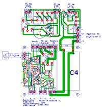
Both boards can be connected together using spacers, but this possibility is not used in this project.
„Block” schema:
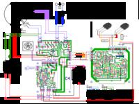
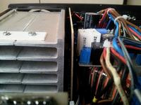
Heat sink with dimensions of 100mm x 160mm x 35mm (base is 5mm thick) was cut in half and built around with laminate so that it creates a tunnel. Air is sucked by front holes in the housing and the fan blows heated air and cools the heat sinks.
Tests:
At the current of 4,3A the temperature after 37 minutes was 60 degrees Celsius and then the moment of switching the fan was set. After switching the fan, the temperature dropped after a minute to 42 degrees Celsius. Another test was shorting the output terminals at the current of 8A, the power supply operated without any problem for 20 minutes.
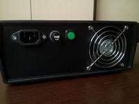
The whole is constructed so it can be easily assembled and disassembled. Front panel was designed in CorelDRAW X4. Two panels were printed. All points for drilling holes in the board were printed on the first one. Another one was laminated to provided a protective layer where is LCD display. 1kohm potentiometers were added for accurate voltage and current regulation. In the back of the housing there is a fuse, power and momentary push button connected to the meter. The whole weighs 4,1kg.
Pictures:
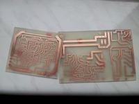
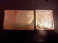
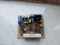
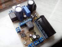
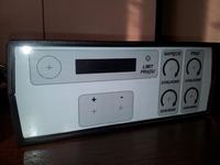
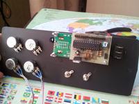

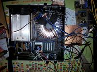
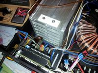
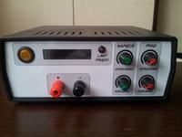
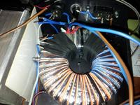
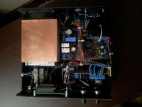
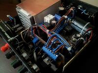
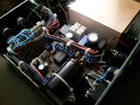
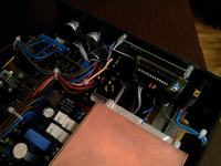
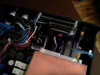
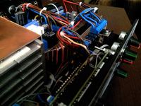
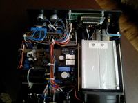
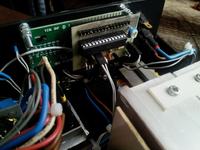
All the PCBs and list of elements can be found at the original thread of the project.
Note! In the second PCB there is a mistake in the list of elements. Controlling transistor TIP32 should be replaced with TIP31/BD139.
Link to original thread (useful attachment) – Zasilacz warsztatowy-laboratoryjny 0-30V/0-8A/200W

