the8thhabit
Newbie level 5

Hello, I'm simulating a wireless power transfer system and I have a question.
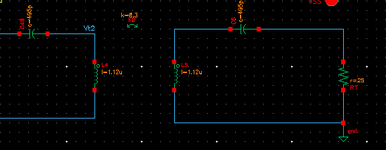
The simulation results are different when the rectifier receives power from the TX as shown in the first figure below and when the RX consisting of the rectifier is converted to an equivalent resistor as shown in the second figure. (Tx is consist of Class-D PA)


I use the equation of Rrect = RL * {8/(π^2)}
The waveform I want is simulated as shown in the first figure with RL, and its result is below.
I would like to know why the same waveform does not appear when I convert it to an equivalent resistor.
All the setup situations are the same, I just changed the rectifier to an equivalent resistor.
I would appreciate your help.
The simulation results are different when the rectifier receives power from the TX as shown in the first figure below and when the RX consisting of the rectifier is converted to an equivalent resistor as shown in the second figure. (Tx is consist of Class-D PA)
I use the equation of Rrect = RL * {8/(π^2)}
The waveform I want is simulated as shown in the first figure with RL, and its result is below.
I would like to know why the same waveform does not appear when I convert it to an equivalent resistor.
All the setup situations are the same, I just changed the rectifier to an equivalent resistor.
I would appreciate your help.


