umery2k75
Advanced Member level 1
high frequency wire melting transformer

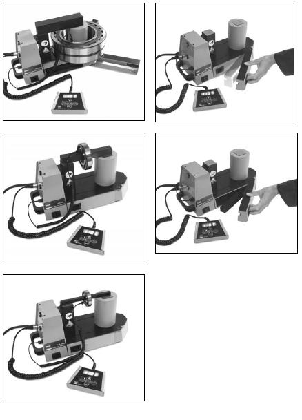
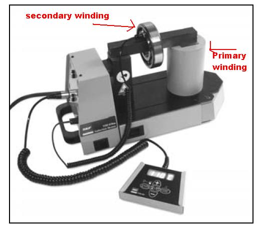
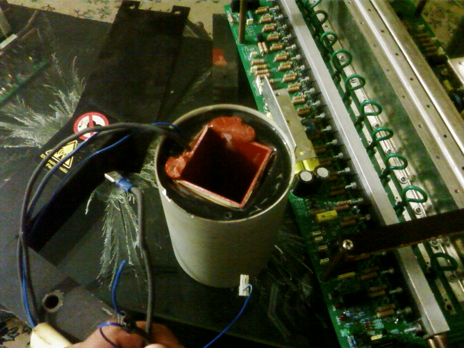
This is a line frequency induction heating device. The picture you see here, is the primary of the transformer. The secondary side of the transformer is not wire.It's a ball bearing.
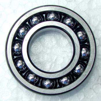
This device works on a very simple principle.In the primary side there are large number of turns, the primary side is the cylinder.At the secondary side only ONE TURN is there. The turn is itself a bearing.The square hole in the cylinder is for the iron core that fits into it, to increase the permeability of transformer.
So, a scheme of transformer that has higher primary turn and lesser secondary turns leads to low voltage and high current, which means I^2.R losses, that means secondary will starts to heat up.Here the I^2.R losses is what we want, for the bearing(secondary 1 turn winding) to heat up.
The power is control by a TRIAC, by variying phase angle, the power being delieverd to the transfomer is varied and thereby temperature of the bearing can be altered.The mechanism of this device is simple. I saw in that device there was a Sticker that means, people who has heart device installed in there body, must stay away from this device. I think they must stay away for atleast 10m as I remember. On the other hand, this is a line frequency transformer, so how come this is harmful to people that have artifical clocks fitted in their body that sends signal to their heart to work.The heart device makes the heart work, according to signals.This is a line frequency tranformer working at 50Hz, the only difference is that the secondary is made of 1 turn and the turn is bearing. So, I don't know why it's harmful to such patients. Secondly, I asked somebody that I want to plug in the primary side of the transformer(White Cylinder) only to see anything, I observe. He said to me, the winding of the transformer would quickly melt.
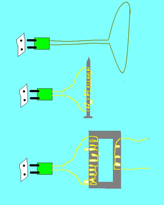
Now if you look at the bottom picture.

I had done such experiment, when I was a kid.Rereing to the first figure. I used to do this by using the Solder Iron Wire. When I power on, the wire burst open from the middle with a blue flash. On those days, circuit breakers were not common and we used to have fuses that were of cement and their wires were made by us.They were reusable fuses.
If you see second picture, such type of circuits with a nail are often given in text books to encourage students and to let them know about the magnetic property that comes into it. I think all such typical example uses the DC power of 9V and it evidently get's it Nort pole and South pole and this whole things begins to react like a magent. I don't know as what would be the behaviour if DC source is removed and AC source is given in.Will nail still be able to attract magnets? If yes, so why don't transformers attract objects like magnets?
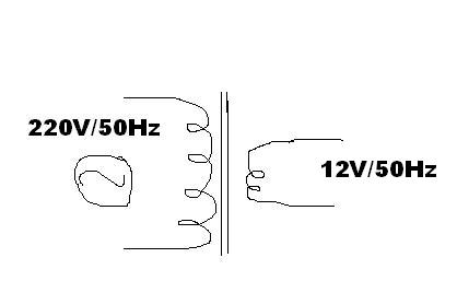
If you see the 3rd picture, it's a typical picture for showing about the operation of transformer.If you see the primary is shorted and secondary is shorted. There must pass a huge amount of current when the transformer is in operation, but all such things don't happen, because primary/secondary might have some impedances.Suppose, this transformer is of 220-12V. I can hook up a 12V bulb and energize it, the bulb begins to glow.Primary and secondary is not getting short and no large amount of current is flowing in primary/secondary.If primary is not getting short, so how come when I energize the primary coild with 50hz 220V will get melt, accroding to some one?

This is a line frequency induction heating device. The picture you see here, is the primary of the transformer. The secondary side of the transformer is not wire.It's a ball bearing.
This device works on a very simple principle.In the primary side there are large number of turns, the primary side is the cylinder.At the secondary side only ONE TURN is there. The turn is itself a bearing.The square hole in the cylinder is for the iron core that fits into it, to increase the permeability of transformer.
So, a scheme of transformer that has higher primary turn and lesser secondary turns leads to low voltage and high current, which means I^2.R losses, that means secondary will starts to heat up.Here the I^2.R losses is what we want, for the bearing(secondary 1 turn winding) to heat up.
The power is control by a TRIAC, by variying phase angle, the power being delieverd to the transfomer is varied and thereby temperature of the bearing can be altered.The mechanism of this device is simple. I saw in that device there was a Sticker that means, people who has heart device installed in there body, must stay away from this device. I think they must stay away for atleast 10m as I remember. On the other hand, this is a line frequency transformer, so how come this is harmful to people that have artifical clocks fitted in their body that sends signal to their heart to work.The heart device makes the heart work, according to signals.This is a line frequency tranformer working at 50Hz, the only difference is that the secondary is made of 1 turn and the turn is bearing. So, I don't know why it's harmful to such patients. Secondly, I asked somebody that I want to plug in the primary side of the transformer(White Cylinder) only to see anything, I observe. He said to me, the winding of the transformer would quickly melt.
Now if you look at the bottom picture.
I had done such experiment, when I was a kid.Rereing to the first figure. I used to do this by using the Solder Iron Wire. When I power on, the wire burst open from the middle with a blue flash. On those days, circuit breakers were not common and we used to have fuses that were of cement and their wires were made by us.They were reusable fuses.
If you see second picture, such type of circuits with a nail are often given in text books to encourage students and to let them know about the magnetic property that comes into it. I think all such typical example uses the DC power of 9V and it evidently get's it Nort pole and South pole and this whole things begins to react like a magent. I don't know as what would be the behaviour if DC source is removed and AC source is given in.Will nail still be able to attract magnets? If yes, so why don't transformers attract objects like magnets?
If you see the 3rd picture, it's a typical picture for showing about the operation of transformer.If you see the primary is shorted and secondary is shorted. There must pass a huge amount of current when the transformer is in operation, but all such things don't happen, because primary/secondary might have some impedances.Suppose, this transformer is of 220-12V. I can hook up a 12V bulb and energize it, the bulb begins to glow.Primary and secondary is not getting short and no large amount of current is flowing in primary/secondary.If primary is not getting short, so how come when I energize the primary coild with 50hz 220V will get melt, accroding to some one?