Continue to Site

Welcome to EDAboard.com

Welcome to our site! EDAboard.com is an international Electronics Discussion Forum focused on EDA software, circuits, schematics, books, theory, papers, asic, pld, 8051, DSP, Network, RF, Analog Design, PCB, Service Manuals... and a whole lot more! To participate you need to register. Registration is free. Click here to register now.

Will this circuit work?

Status
Not open for further replies.

nicholasdk

Newbie level 5
Newbie level 5
Joined
Mar 3, 2013
Messages
8
Helped
0
Reputation
0
Reaction score
0
Trophy points
1,281
Activity points
1,348
Hi guys. I'm building a portable soundsystem, and i want some lights on it. I'm thinking of using this guide to get some flashing. I was wondering it this circuit will work? It's 20 LED blurbs with some resistors. I have mainly 2 questions. Which resistors should i choose, i red someting about 1 ohm resistors, is this correct? Can i connect the TiP31 to the loudspeaker, with the red (+??) wire and the black (-??)(ground??) wire? Or can you only connect is by the jack stick? Overall, will this circuit work? Thank you for your help..

Lys på anlæg.png
 

The resistor values depend entirely on the kind of LEDs you are using, the value can't be predicted without knowing their forward voltage drop and the current you intend them to pass.

TIP31 has emitter, base and collector pins, you don't show which is which. It might work if you connect the negative side of the battery and the 'ground' side of the loudspeakers to the emitter pin, the other side of the loudspeaker to the base pin through a resistor (100 Ohms is a good starting value) and connect the collector to R1 - R5. Don't expect spectacular results but they should then flash.

Brian.
 

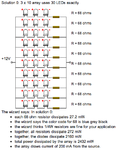
I'm thinking about using some forward voltage 3v-3,6v with forward current 20mA. I used a caluctalor and found out that I should use a parallel connection with 3 led's and some 68ohm resistors, is this correct? Skærmbillede 2013-03-03 kl. 16.14.06.png

If I connect some kind of switch, will that require some kind of resistor also?
 

The second circuit will work but not the first one. The reason is that each LED when lit will have up to 3.6 V across it so each chain of 4 would need (4 * 3.6) 14.4V to operate and you only have a 12V supply.

The resistor value is easy to work out. The voltage across the LED is called Vf and the current you want it to pass is called ILed:

R = (Supply voltage - (number of LEDs * Vf)) / ILed.

For example with 12V supply and three LEDs, each with Vf of 3.6V and with your desired current being 20mA (0.02A):

R = (12 - (3 * 3.6)) / 0.02 = 60 Ohms.

If you run LEDs without a resistor they WILL burn out and very quickly!

Brian.
 

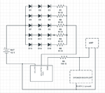
I looked at your comments and made i new circuit. I hope this is correct, because I really wants this to work. And, betqixt, thank you for your answers so far. I'm sorry for all the (stupid) questions, but it's my first DIY project. It's for a portable soundsystem for a festival. :) Skærmbillede 2013-03-03 kl. 21.28.41.png
 

Don't expect spectacular results but they should then flash.
The most simple "light organs" I ever saw had at least band-pass filters and rectifiers, translating sound level of different frequency bands to light intensity. There performance had been acceptable in the 60th and early 70th years. Later on, sound triggered light sequencers achieved much more impressive effects.

I'm sure you'll find a lot of better "light organ" circuits on the web.
 

The circuit is correct but all it will do is light up all the LEDs when a certain volume level is reached. As FvM points out, you can make far more 'spectacular' displays if you split the audio spectrum and drive different colored LEDs (Red for bass, blue for treble etc.) or make the LEDs follow pattern sequences decided by volume or tone.

I have no idea how powerful your amplifier is but should you find the LEDs light up when the volume is too low, add another resistor or a 1K variable resistor between the transistor base and emitter pins. It will set the volume threshold that makes the LEDs light up.

Brian.
 

The voltage from an amplifier output is AC that swings positive and negative. The maximum allowed negative voltage for a TIP31 and for most transistors is only 5V which is an output from the amplifier that is only 1.56W into an 8 ohm speaker that is not loud.

You need a diode from the base to emitter to conduct when the base voltage is higher than -0.7V.

The LEDs will not light properly because you need a peak detector circuit for them.
 
  • Like
Reactions: FvM

    FvM

    Points: 2
    Helpful Answer Positive Rating
Status
Not open for further replies.

Part and Inventory Search

Welcome to EDABoard.com

Sponsor

Back
Top