Continue to Site

Welcome to EDAboard.com

Welcome to our site! EDAboard.com is an international Electronics Discussion Forum focused on EDA software, circuits, schematics, books, theory, papers, asic, pld, 8051, DSP, Network, RF, Analog Design, PCB, Service Manuals... and a whole lot more! To participate you need to register. Registration is free. Click here to register now.

Why vp is going low in cross coupled?

Status
Not open for further replies.

niteshtripathi

Member level 3
Member level 3
Joined
Oct 11, 2013
Messages
59
Helped
0
Reputation
0
Reaction score
0
Trophy points
6
Activity points
429
Capture.PNG

The voltage at node P falls at the crossings of VX and VY if M1 and M2 do not enter the triode region at any point. On the other hand, if each transistor enters the deep triode region in a half cycle, then VP is low most of the time and rises at the crossings at VX and VY .

My question is that why vp is going low?
 

Starting from a text book description of the cross-coupled pair, when one of the input goes high by delta_v amount and another input goes low by delta_v amount, the tail node voltage does not change and the (small-signal) current through one transistor is given by gm(delta_v) and the through the other transistor by gm(-delta_v). The small signal current flows in a circular loop.

Now when Vx=Vy in your case, both the transistors need to carry the same current. The drop in Vp is because of the Vgs requirement of M1 and M2 to carry Itail/2. The value of Vp you see is roughly the DC voltage you would see if you had tied both your inputs to the same voltage (=Vx=Vy). But as Vx starts moving away further and further higher and Vy the other way, because of the square law nature of the device, Vp needs to go back up.
 
Can you explain it more, vivekroy? thanks.
 

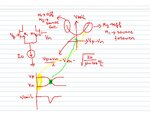
Please see the attached image.
When (Vp-Vn) is high, M2 is off and M1 behaves as a nice source follower with a current of Io. Similarly when (Vp-Vn) is highly negative, M1 is off and M2 behaves as a source follower. During this two time duration, shown in yellow and green in time domain waveform at the bottom, Vtail =Vp or Vn - Vgs(for a current of Io). When the two input voltages are equal, the tail node is at the lowest possible voltage which causes the dip in the tail node voltage.

tail_node_dipping.JPG
 
That explanation is very great, thanks.

The source voltage will follow the gate voltage as a voltage follower as you mentioned.
 

Status
Not open for further replies.

Similar threads

Part and Inventory Search

Welcome to EDABoard.com

Sponsor

Back
Top