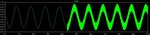
Why the signal oscillates @ 100KHz in the transient analysis?
- Thread starter AAOAA
- Start date
- Status
- Not open for further replies.


- Joined
- Jul 4, 2009
- Messages
- 16,648
- Helped
- 5,158
- Reputation
- 10,349
- Reaction score
- 5,251
- Trophy points
- 1,393
- Location
- Aberdyfi, West Wales, UK
- Activity points
- 140,893
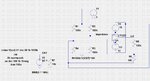
Check your simulation circuit, you have R6 shorted out and possibly a missing ground at R3 and R4.
Brian.
Brian.

Audioguru
Advanced Member level 7
- Joined
- Jan 19, 2008
- Messages
- 9,461
- Helped
- 2,152
- Reputation
- 4,304
- Reaction score
- 2,012
- Trophy points
- 1,393
- Location
- Toronto area of Canada
- Activity points
- 59,764
Your circuit is missing the very important supply bypass capacitors shown and talked about in the datasheet.
So read the datasheet!
So read the datasheet!
Audioguru
Advanced Member level 7
- Joined
- Jan 19, 2008
- Messages
- 9,461
- Helped
- 2,152
- Reputation
- 4,304
- Reaction score
- 2,012
- Trophy points
- 1,393
- Location
- Toronto area of Canada
- Activity points
- 59,764
Missing supply bypass capacitors do not affect the phase of the input and output. It allows the output to feed into the input through the power supply.
crutschow
Advanced Member level 6
- Joined
- Feb 22, 2012
- Messages
- 4,572
- Helped
- 1,006
- Reputation
- 2,010
- Reaction score
- 1,164
- Trophy points
- 1,393
- Location
- Colorado USA Zulu -7
- Activity points
- 26,057
Your op amp power supplies also need to be grounded.
LvW
Advanced Member level 6
Thank u so much for your replys. But is the bode plot useless at this point (since the phase @ 100KHz doesnt indicate for oscillation)?
It would be interesting (better: important!) to know what your BODE plot shows. Which transfer function?
godfreyl
Advanced Member level 5
This is all in a simulation, right? Quite likely there is no oscillation, your simulator's just misbehaving. Try changing the minimum timestep for your transient analysis. That may solve the problem.
LvW
Advanced Member level 6
I don`t think so. The time steps seem to be OK - look at the simulation results, they look smoothly. Don`t blame the simulator - in nearly 100% of all cases it is not the simulation engine but the user who shows "misbehaving".This is all in a simulation, right? Quite likely there is no oscillation, your simulator's just misbehaving. Try changing the minimum timestep for your transient analysis. That may solve the problem.
Audioguru
Advanced Member level 7
- Joined
- Jan 19, 2008
- Messages
- 9,461
- Helped
- 2,152
- Reputation
- 4,304
- Reaction score
- 2,012
- Trophy points
- 1,393
- Location
- Toronto area of Canada
- Activity points
- 59,764
In the schematic, the signal source is not connected to the circuit.
What is the input of the circuit? Is the input the line that is spelled wrong "impedence"?
What is the input of the circuit? Is the input the line that is spelled wrong "impedence"?
- Joined
- Jan 22, 2008
- Messages
- 53,710
- Helped
- 14,812
- Reputation
- 29,921
- Reaction score
- 14,445
- Trophy points
- 1,393
- Location
- Bochum, Germany
- Activity points
- 303,649
Apart from the question if it's a reasonable circuit and if every detail is connected as intended, you obviously did not measure loop gain.
Measuring loop gain right shows about 50 dB DC gain and multiple crossings of the 0 dB line.
Measuring loop gain right shows about 50 dB DC gain and multiple crossings of the 0 dB line.
It is, by a behavioral expression for R3 resistance.In the schematic, the signal source is not connected to the circuit.
AAOAA
Junior Member level 2
- - - Updated - - -
Actually, I got this circuit from application note of Linear Technology, with other Opamps it works well. Could you tell me please how you measured the loop gain to be 50dB?
Thanks...
http://cds.linear.com/docs/en/application-note/an43f.pdf
Apart from the question if it's a reasonable circuit and if every detail is connected as intended, you obviously did not measure loop gain.
Measuring loop gain right shows about 50 dB DC gain and multiple crossings of the 0 dB line.
It is, by a behavioral expression for R3 resistance.
Actually, I got this circuit from application note of Linear Technology, with other Opamps it works well. Could you tell me please how you measured the loop gain to be 50dB?
Thanks...
http://cds.linear.com/docs/en/application-note/an43f.pdf
Last edited:
Audioguru
Advanced Member level 7
- Joined
- Jan 19, 2008
- Messages
- 9,461
- Helped
- 2,152
- Reputation
- 4,304
- Reaction score
- 2,012
- Trophy points
- 1,393
- Location
- Toronto area of Canada
- Activity points
- 59,764
The voltage gain of your opamp is 1+ (R5/R6)= a little more than +60dB.
- Joined
- Jan 22, 2008
- Messages
- 53,710
- Helped
- 14,812
- Reputation
- 29,921
- Reaction score
- 14,445
- Trophy points
- 1,393
- Location
- Bochum, Germany
- Activity points
- 303,649
Loop gain can be e.g. determined by Middlebrook's method. It has been quite often discussed at Edaboard, some examples:
https://www.edaboard.com/threads/300916/
https://www.edaboard.com/threads/177993/
Regarding bridge circuit stability, the problem in this case is PSRR and it's frequency characteristic. Apart from the question, if floating supply is a good means for practical amplifier design, it's really a bad idea to implement it with a 500 MHz amplifier like LT1222. If you look thoroughly on your simulation, you'll notice that the oscillation frequency is around 80 MHz, not 100 kHz.
Borber
Advanced Member level 5
- Joined
- Dec 31, 1999
- Messages
- 1,600
- Helped
- 236
- Reputation
- 474
- Reaction score
- 111
- Trophy points
- 1,343
- Location
- on third flor
- Activity points
- 11,863
By the way capacitor bypassing of power supply in simulation is not needed because power supply impedance is 0ohm or 1mohm depends on parameters settings in simulation software.
- Status
- Not open for further replies.
Similar threads
-
-
Why does the voltage transfer curve (VTC) shift?
- Started by lufer17
- Replies: 1
-
PI controller effect on the DC of error signal in PLL
- Started by yefj
- Replies: 17
-
How to check the stability analysis of completx opamp circuit in Ltspice
- Started by newbie_hs
- Replies: 19
-
Transient noise different than Pnoise verilogA
- Started by InvokeMeWell
- Replies: 1