Hi Twlin1,
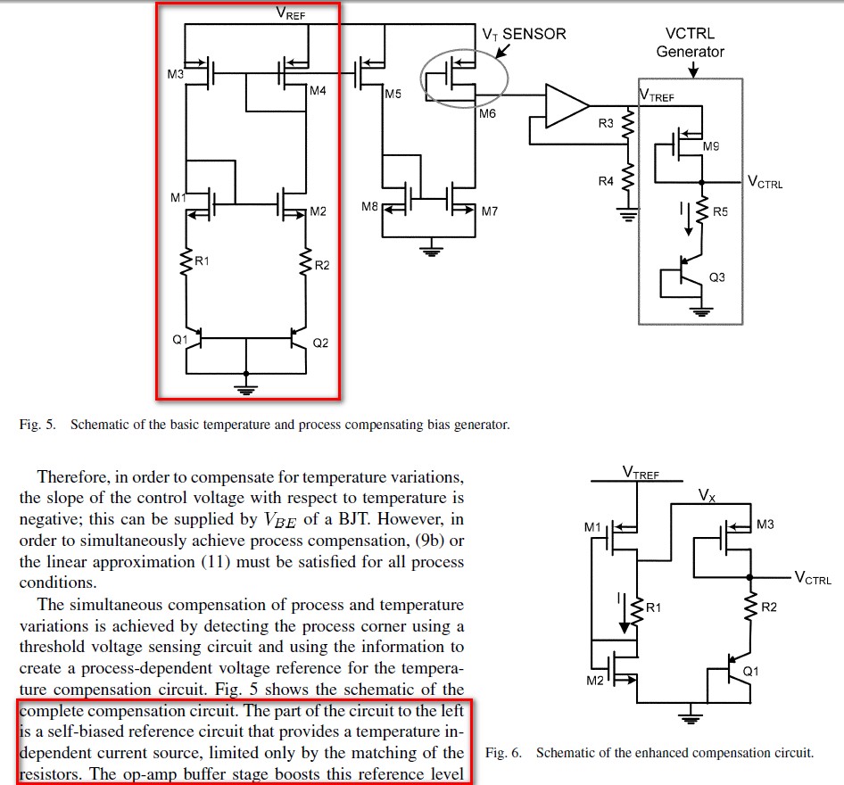
I believe the circuit balances the negative temperature coefficient of a VBE against the positive kT/q temperature coefficient of the difference in two VBE's. Specifically, although not shown in the figure, the two pnp devices are likely sized differently. One might be 8 or 10 times the size of the other. When one forces the current in the two to be the same, the difference between the two voltages and series resistors is forced to near zero at the sources of M1 and M2. In a simpler implementation where only R2 is present, the resulting current is, I = VT*ln(N)/R2 where VT is the thermal voltage kT/q and N is the ratio of the area of Q2 to Q1. With two resistors the equation is a bit more complex.
I hope this helps!