T
treez
Guest

Hello
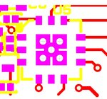
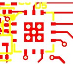
The 25th page of the below app note shows the land pattern of an offline linear LED driver IC.
The FETs in this package operate in the linear region.
Why is the land pattern showing a central thermal pad of dimension just 3mm by 3mm?
There is room there to make it 4mm by 4mm and still have plenty of clearance away from the actual outer pads. The solder mask could still be 3mm by 3mm so that the IC “locates” in the centre of the land pattern during the reflow soldering process.
So why have the manufacturers not recommended a bigger thermal pad for this IC?
DT3001 LED driver IC
http://www.seoulsemicon.com/_upload/Goods_Spec/Acrich2-Applicationnote.pdf


