EE18
Newbie level 4

I am fairly new to using PrimeTime and so am playing with a few toy examples using cells from the default lsi_10k.lib cell library.
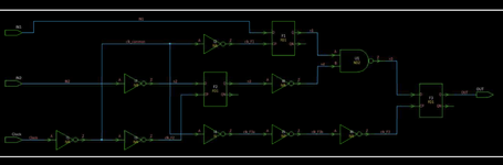
I am simulating the attached schematic (please advise if you want me to post the gate-level netlist as well) with the constraints below:
I am simulating the attached schematic (please advise if you want me to post the gate-level netlist as well) with the constraints below:
I obtain the setup timing report below:#-----------------------------------------------#
# ENFORCE CONSTRAINTS
#-----------------------------------------------#
# Define clock plus its natural latency
create_clock -name CLK -period 10 [get_ports Clock]
set_input_delay -clock CLK 2 [all_inputs]
set_output_delay -clock CLK 2 [all_outputs]
#-------------------------------------------------#
# DO STA
#-------------------------------------------------#
# Update timing (this is where delay calculations and timing analysis are done)
update_timing
#-------------------------------------------------#
# REPORTS
#-------------------------------------------------#
# Setup timing report
report_timing -delay max -max_paths 1 -path_type full_clock_expanded \
-slack_lesser_than 1000000 > timing_report_setup.txt
# Hold timing report
report_timing -delay min -max_paths 1 -path_type full_clock_expanded \
-slack_lesser_than 1000000 > timing_report_hold.txt
As you can see, the critical path is from the final flop (F3) launching towards the output port. No problem here. The only issue is, why is my clock network being taken as ideal? My clock tree clearly has inverters on it. I would expect to see an arrival time > 0 at my launching flop's clock pin (F3/CP) and yet it is precisely 0. What am I doing wrong? Similarly, in my hold analysis, there is no accounting for clock skew.g****************************************
Report : timing
-path_type full_clock_expanded
-delay_type max
-slack_lesser_than 1000000.00
-max_paths 1
-sort_by slack
Design : MyComp
Version: T-2022.03
Date : Sun Aug 11 12:38:45 2024
****************************************
Startpoint: F3 (rising edge-triggered flip-flop clocked by CLK)
Endpoint: OUT (output port clocked by CLK)
Path Group: CLK
Path Type: max
Point Incr Path
---------------------------------------------------------------
clock CLK (rise edge) 0.00 0.00
clock network delay (ideal) 0.00 0.00
F3/CP (FD1) 0.00 0.00 r
F3/Q (FD1) 1.37 1.37 f
OUT (out) 0.00 1.37 f
data arrival time 1.37
clock CLK (rise edge) 10.00 10.00
clock network delay (ideal) 0.00 10.00
clock reconvergence pessimism 0.00 10.00
output external delay -2.00 8.00
data required time 8.00
---------------------------------------------------------------
data required time 8.00
data arrival time -1.37
---------------------------------------------------------------
slack (MET) 6.63
1