Continue to Site

Welcome to EDAboard.com

Welcome to our site! EDAboard.com is an international Electronics Discussion Forum focused on EDA software, circuits, schematics, books, theory, papers, asic, pld, 8051, DSP, Network, RF, Analog Design, PCB, Service Manuals... and a whole lot more! To participate you need to register. Registration is free. Click here to register now.

Why a popular circuit for opto-isolating 24 V inputs to 5V/3.3V is a divider before optocoupler LED?

Status
Not open for further replies.

Auric_

Junior Member level 2
Joined
Jul 30, 2023
Messages
20
Helped
0
Reputation
0
Reaction score
0
Trophy points
1
Activity points
358
Hello everyone.
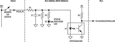
If you look at the input circuit of almost every programmable controller that works with 24V discrete signals, you will see the following circuit (or functionally similar):
circuit.png
I want to understand, what functions are imposed on the voltage divider on R1 and R2 (don't pay attention to R3-D1 circuit, it may not exist, just as its installation may be before R1).
The actuation voltage can be achieved by selecting R1 and R5, and the device input current is rarely required to be greater than the resulting optocoupler LED current.
If you read, for example, this document, you can understand that resistor R2 is involved in setting the input current of the device, I have not yet realized another function and I will be very glad to receive an explanation regarding the presence of R2 in the circuit, as well as some technique that can give calculation of these parameters (resistances) of the circuit.
PS: Well, R2 can also dampen differential nanosecond interference, but C1 can also cope with this.
 

Hi,

if you want to understand the function, you need values.

R2 for example could be in the Megaohms, just to discharge C1.
Or it could be in the 100 Ohms for fast swithc-OFF of the optocoupler.
Or it could be in the kiloOhms just to adjust the hysteresis / thresholds.

Klaus
 

Hello everyone.
If you look at the input circuit of almost every programmable controller that works with 24V discrete signals, you will see the following circuit (or functionally similar):
View attachment 185317

If you read, for example, this document, you can understand that resistor R2 is involved in setting the input current of the device, I have not yet realized another function...R2 can also dampen differential nanosecond interference, but C1 can also cope with this.
There is no other function. You can apply the Thevenin equivalent circuit principle here to determine the U1 IR LED current. However since IR diodes are lower voltage than visible LEDs, this design will fail to illuminate D1. Thus a series R is needed at the U1 input. It is possible to compute values for R3 and R(U1) to say 5 mA each and eliminate R2.

R2 can not dampen ns interference unless there is some inductance not shown in your logic diagram such as a long wire with some resonance with C1. Shielding the wire with twisted pair is a better way for immunity.

There are many ways to design this better, but first, you need to define all the SPECS for currents, switch bounce time, latency, & ESD protection.

 
Hi,

if you want to understand the function, you need values.

R2 for example could be in the Megaohms, just to discharge C1.
Or it could be in the 100 Ohms for fast swithc-OFF of the optocoupler.
Or it could be in the kiloOhms just to adjust the hysteresis / thresholds.

Klaus
Usually R1 is about 4-6 kOhm (although it can be less, for example about 2.2 kOhm as in the document on the hyperlink) and R2 is from 500 Ohm to 1 kOhm (but this is all approximately). But in most cases, R1 is greater than R2.
For the third option, “setting the threshold/hysteresis” - it’s clear to set the threshold, but setting the threshold for voltage can be done without it [R2], but for current - yes it is involved, but it’s not entirely clear why it's need to adjust the current, because the input current is not it is required to increase if it is already at 9-10mA and without additional R2 in the circuit (only R1, we are not talking about C1 yet, since we are talking about current).
By the way, the second half of the option - setting the hysteresis - I don’t quite understand how R2 is involved? More precisely, I don’t quite understand its uniqueness in this process, I tried to adjust the hysteresis with an optocoupler, but without a Schmitt trigger at the output it is useless, and an optocoupler with a linear current amplification section is required. If we consider those conditions, so the thresholds depend primarily on R1 and R5 (as does setting the voltage thresholds), setting R2 also moves them, but not to the same extent, but the hysteresis width did not change in either case. I would like to understand this too, but I don’t quite understand the calculation method and the influence of R2 in general, which is why I opened the topic.
With the first two options about the C1 discharge it is clear, since C1 is necessary, then it is also necessary to fight against its negative influence, since the PLC does not always have both “zero” and “one” voltages at the input, sometimes “one” exists (the circuit is energized at 24V), but “zero” is realized by breaking the input circuit, and C1 is not discharged through the input circuit.
 

Considering that the above circuit is an interface used on the automation scope, where distinct GNDs are often used for the general logic, for input and output, it makes a lot of sense that an additional function of the resistive divider is to protect the optocoupler against overvoltage, in this case of a reverse-biased connection from the 'field'.
 

Considering that the above circuit is an interface used on the automation scope, where distinct GNDs are often used for the general logic, for input and output, it makes a lot of sense that an additional function of the resistive divider is to protect the optocoupler against overvoltage, in this case of a reverse-biased connection from the 'field'.
Well, if we look at such circuits in detail, then either there are AC optocouplers, or rectifier bridges, or the circuit is clearly designed for connection and otherwise will be cut off by a diode, for example. That is, this option will probably be among the last, if you look at practice, in theory, of course, someone could use it.
I am inclined to believe that capacitor C1 is needed to protect against differential noise, but its discharge is not provided for in a circuit without a divider - this is really bad. Again, in practice, set R2 parallel to optoLED actually gives results even without C1, since the capacitance is already present on the wires, the optocoupler itself, and again, the duration of the interference can charge the capacitor, and R2+C1 will allow more in the fight against interference than C1 alone.
 

Hi,

The D1 and R3 circuit does not work this way - usually.

***
C1 parallel to the OC_diode makes the timing unsymmetric.
Because at switch ON the capacitor voltage needs to rise from 0V to about 1.2V (where it stalls)
but at turn OFF it needs just go down from 1.2V to 1.1V (or so).
This may be good or bad ... according your requirements.

***

hysteresis:
Let´s calculate back from microcontroller input:
let´s say the microcontroller Has VIH of 2.2V and VIL of 0.9V and R5 is 10k and a OC_CTR 50% and a OC_Vf of 1.2V.

thus the optocoupler collector currents are: 0.28mA and 0.41mA respectively.
with the CTR the OC_diode currents are 0.56mA and 0.82mA.

If R2 = 500R, then this means a current of 2.4mA, so raising the thresholds to 2.96mA and 3.22mA.
Now if you have a 24V input you may want the input threshold to be at 16V maybe.
Thus you need R1 to be 4.6k Ohm. Resulting in a LOW treshold of 14.8V

But if you use R2= 5k then you get a current of 0.24mA and thresholds of 0.80mA and 1.06mA respectively
So you need R1 to be 13.9k to - again - get a 16V HIGH threshold.
But then you get a 12.3V LOW threshold. (before it was 14.8V)

For sure it varies the speed and the power dissipation, too.
Also it has influence on turn ON and turn OFF timing.

*****
Please do the calculations according your requirements.

Klaus
 
You will never find this circuit with the Status LED + R across the IR in U1. Almost all LEDs are limited to VR=-5V . R2 clearly attenuates 24V but there may also be a large inductive flyback voltage so normally TVS diodes may be added for protection from all sorts of interference should be seriously considered.
1696615422258.png
 

if we look at such circuits in detail, then either there are AC optocouplers, or rectifier bridges,
I don´t think so. This application looks like for 0V/24V DC signals .. thus it does not necessarily need an AC optocoupler nor a rectifier.

Klaus
 

I don´t think so. This application looks like for 0V/24V DC signals .. thus it does not necessarily need an AC optocoupler nor a rectifier.

Klaus

here is a Siemens S-7 1200, there is a bridge from BAV99 before 063L, if memory serves correctly.
What I mean is that the PLC sometimes uses SINK current and sometimes use SOURCE current connection of PLC input, and bridge is used to protect against reverse connection of optoLED.
6ES7214_1AG40_04.jpg
In general, thank you very much for the comments, I looked at the question a little more broadly and the answers began to come on their own, and special thanks for the hysteresis (calculation).
Now at the same time I’m trying to figure out https://toshiba-semicon-storage.com/info/application_note_en_20210325_AKX00763.pdf?did=70620 there is also something useful there.
Regarding R3+D1, oh, this turned out to be a very unfortunate scheme, it would be better to erase them :)
 

Hi,

I don't get the whole schematic of the S7. But I guess here the input is not GND referenced like in post#1.

I've designed PLC like applications ... I wish I had the very detailed Toshiba application note then. On the other side it misses the timing considerations, which were very important with my applications.

Klaus
 

I believe your question is completely answered in the post #1 link. R1 and R2 should be selected so that the specified voltage and current levels are achieved:

1696668127912.png


Hysteresis may be useful, but is not implemented by the shown circuit.
 

Hi,
Hysteresis may be useful, but is not implemented by the shown circuit.
I fully agree.
In post#1 I wrote "hysteresis / thresholds" because we don't know the microcontroller input functionality.
If the microcontroller has some "schmitt trigger type" input, then this also applies to the PLC type input.

Klaus
 

Thank you, colleagues, for the advice, I did the calculation using the example from Toshiba, but I have a desire to work with a transistorized optocoupler, at the output I will put a buffer element with a Schmitt trigger at the input, such as 74HC..., and there is a problem - I don’t quite understand, when the table indicates the range of possible CTR values, for example from 15% to 50% (I need CTR in order to move from current R2 or Rup to calculating the current on serial R1), but I don’t understand, this range is given for certain conditions, for example IF = 16 mA, TA = 25°C, do I understand correctly that these deviations need to be applied to the boundary values, taking into account the IF current and IF temperature found from the graphs in the datasheet? For example, for the minimum voltage to check the shutdown condition, the minimum voltage Vf and the maximum possible CTR are selected so that even under these conditions the selected minimum resistance “turns off” the optocoupler at 5V. So it turns out that you need to multiply 50% by another 1.1 when the temperature rises to 50°C? Or do the values indicated in the table already contain a possible spread of values?
Similarly, with the search for the maximum resistance, to ensure that the optocoupler is “switched on” at a minimum CTR and a maximum voltage Vf (Although there is also a problem here - Vf and CTR have different dependences on temperature - the voltage Vf drops with increasing temperature, and CTR increases with increasing temperature, What to choose is the question of what will be more important).
 

Hi,

if you want to know the very limits you need to calculate through the worst cases.

But usually one does not want to go to the limits.

Let´s say you have calculated: VIH of 2.2V and VIL of 0.9V.
Then drive it HIGH by way more than 2.2V --> let´s say >3.0V
and drive it LOW at much lower input voltage --> let´s say >0.4V

The test conditions mainly are given in the datasheet so you know - and also can verify the specifications.
Also you may have charts the show you how the values differ on different operting conditions.

From my experience with optocouplers:
The maximum given in the datasheet will usually not be stepped over.
But with aging the minimum wil go lower and lower.

I made a bad experience when the CTR of optocouplers went down to less than 30% related to the specified CTR after less than 5 years of operation. (almost 24/7).
Thus I can only recommend not to go to close to the specified limits. This does not mean you have to overdrive the input LED, you may also reduce the thresold at the optocoupler output.
But it depends on a lot of application variables....

Klaus
 

TIPS
  1. The TLP2363 has no CTR specs because it is not a simple phototransistor with coupling loss and hFE gain then overall near 100% CTR or worse. Rather it has a low gain comparator to drive the open collector.
  2. For a standard on-off switch one does not have to think about CTR's here and just use the standard currents in the datasheet tables which are 5 mA and 0 mA.
  3. The If thresholds are plotted in the datasheet around 1 mA +/-0.2
  4. This is a high-speed device so lower impedances are used with higher currents as needed to reduce latency.
  5. One might choose to avoid saturation times and get higher speed data using 100% to 10% current.
  6. If there is any inductance on the wire to switch, then a reverse clamp diode is essential.
  7. The capacitor is useful to attenuate EMI does not need to be large using Zc(f) and impedance of possible source spectrum interference.
  8. The LED indicator may either go in series or in shunt another series R before the IR LED for current limiting defined by the voltage drop between different LEDs with their specs. e.g. 3V for Green at 5mA and 1.5 V +/- 10% for IR @ 2.6 mA
  9. This tells me all I need for reliable operation is 0 to 2.6 mA , if the threshold is around 0.9 to 1.2 mA
  10. If latency is a concern, choose 7.5mA with guaranteed (by design) specs in the table,
  11. For general purpose, PWM choose 5 mA with a large resistor like 1k from 5V because the PWM distortion increases with a smaller input R according to the plots.
 

This is your title question, somewhat overlooked.

>Why a popular circuit for opto-isolating 24 V inputs to 5V/3.3V is a divider before optocoupler LED?

Purpose

This loads the IR diode when 0 input current is applied so that the high impedance state of the LED is not affected by stray EMI.
Radiate E-fields are high impedance are attenuated using this method,

Examine the impedance by the ratio of V/I in the Acceptance are for ON.

This plot implies the impedance needs to be <= 15kohm for the acceptance region. Lower impedance circuits are expected to have higher immunity to EMI.

IEC 61131-2 Type 1 voltage/current operating area
1697925605806.png

The datasheet says "TLP2363 ensures not only the maximum threshold input current but also the minimum value, which contributes to simplifying the design of the input module according to the operating area shown in Fig. 1."
 

Status
Not open for further replies.

Part and Inventory Search

Welcome to EDABoard.com

Sponsor

Back
Top