Continue to Site

Welcome to EDAboard.com

Welcome to our site! EDAboard.com is an international Electronics Discussion Forum focused on EDA software, circuits, schematics, books, theory, papers, asic, pld, 8051, DSP, Network, RF, Analog Design, PCB, Service Manuals... and a whole lot more! To participate you need to register. Registration is free. Click here to register now.

When simulating center tapped inductor in ADS

Status
Not open for further replies.

jwonoh

Newbie level 5
Newbie level 5
Joined
Jul 31, 2019
Messages
8
Helped
0
Reputation
0
Reaction score
0
Trophy points
1
Activity points
98
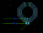
Hello, I'm drawing and testing center-tapped inductor with ADS simulator. Center-tap will be connected to VDD.

After drawing inductor,
I assigned term 1&2 to two ends of inductor and term3 to center tap to simulate s-parameter simulation.
Setting of term impedances are defaults ( 50ohm ).

But I think I have to set impedance of term3 to 0 ohm because it will be connected to the VDD.
Do I have to set impedance of term 3 as a default? or some other value?

Thank you
 

Leave the port impedances set to 50 Ohm. The circuit simulator later takes care of the calculating the voltages and currents for the external impedances connected to the model. S-parameters don't work for 0 Ohm reference impedance.

When you evaluate results for your inductor in differential configuration, the center tap is at 0V due to symmetry anyway.
https://muehlhaus.com/support/ads-application-notes/inductor-em-ports
 

Thank you for your reply:grin:

May I ask one more question?
I've learned that Q of center-tapped is higher than not tapped one and I wanna exploit this feature.
Also, in my idea, inductor of inductance of L1 is divided by factor of 2 when we use center-tap.

However, my center-tapped inductor shows higher inductance and lower SRF.
So, I'm confused and I'm not convinced with my simulation.

If you have any idea about this phenomenon, please let me know. Thank you.

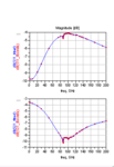
Below figure is my simulation setting and S-parameter plot of it
캡처.PNG
캡처2.PNG


There is no port 3 in your linked post. Which is fine.

- - - Updated - - -

I've learned that Q of center-tapped is higher than not tapped one

I am working on these inductor simulations for many years, and never heard that. The center tap is a virtual ground when used with symmetric excitation. I think you might refer to differential vs. common mode Q factor.

Also, in my idea, inductor of inductance of L1 is divided by factor of 2 when we use center-tap.

I'm not sure what you compare, the full inductor (port 1 to port 2) vs. half of the inductor (port 1 to port 3)? Have a look at my appnote linked above. The important thing is to use the correct excitation - if you drive the inductor single ended from port 1 only, it behaves differently from the differential excitation. Also, that single ended excitation is not the typical use case. You should investigate differential operation.
 
Last edited:

See https://designers-guide.org/forum/YaBB.pl?num=1205240723#9

I've learned that Q of center-tapped is higher than not tapped one and I wanna exploit this feature.
R0=50
Sdiff = (s11-s12-s21+s22)/2.0
Zdiff = 2*R0*(1+Sdiff)/(1-Sdiff)

freq = xval(s11)
Ldiff = imag(Zdiff)/(2*pi*freq)
Qdiff = imag(Zdiff)/real(Zdiff)

Z1 = 1/y11
L1 = imag(Z1)/(2*pi*freq)
Q1 = imag(Z1)/real(Z1)
https://designers-guide.org/forum/YaBB.pl?num=1205240723#8

Qdiff > Q1

Also, in my idea, inductor of inductance of L1 is divided by factor of 2 when we use center-tap.
However, my center-tapped inductor shows higher inductance and lower SRF.
So, I'm confused and I'm not convinced with my simulation.
Consider Ldiff not L1.
Ldiff= 2*(Ldiff/2)

Then I think your math is wrong for 3-port simulation.
It is valid for 2-port simulation.
It is valid for differential mode excitation.

For evaluation of L1 and Q1, port-3 must not be connected.
 
Last edited:

I couldn't see the proof of Qdiff>Qse ??
 

I couldn't see the proof of Qdiff>Qse ??

My test was to check if pancho's equations also work to create differential data from 3-port S-params where the center tap is connected. That indeed works.

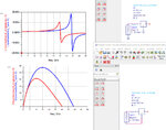
Here is the comparison of single ended and differential Q for that exact same layout, from the same EM simulation:

single_vs_diff.jpg
 
Last edited:

If we consider the equivalent circuit of an inductor and when we make short circuit P2, corresponding distributed components are becoming short circuit.
So, the difference which coming from SE and DIFF measurements might be result of this error. I'm saying that is an error because it does not sound very healthy to me.
In my opinon , DIFF measurement looks like more healthy..
 

If we consider the equivalent circuit of an inductor and when we make short circuit P2

What post and P2 do you refer to? In my post #11 the center tap is at Port 3 and that's floating in this comparison.

The difference between single ended Q and differential Q is also seen for the 2-port case, not related to center tap. You are correct that it can be understood by looking at the shunt path in the equivalent circuit.

inductor_z1port.PNG

inductor_z2port.PNG
 

Status
Not open for further replies.

Similar threads

Part and Inventory Search

Welcome to EDABoard.com

Sponsor

Back
Top