Continue to Site

Welcome to EDAboard.com

Welcome to our site! EDAboard.com is an international Electronics Discussion Forum focused on EDA software, circuits, schematics, books, theory, papers, asic, pld, 8051, DSP, Network, RF, Analog Design, PCB, Service Manuals... and a whole lot more! To participate you need to register. Registration is free. Click here to register now.

What's wrong with Multisim?

Status
Not open for further replies.

umery2k75

Advanced Member level 1
Joined
Apr 19, 2006
Messages
434
Helped
42
Reputation
82
Reaction score
16
Trophy points
1,298
Location
Pakistan
Activity points
5,748
multisim giving me wrong results

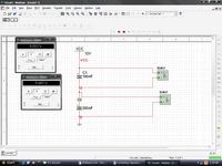
I was just playing with the multisim and I thought of making a series circuit consisting of two capacitors just for nothing.
C1=0.1uF
C2=0.2uF

Vcc=12V

so Vc1=C2/(C1+C2)*Vcc=8V
Vc2=C1/(C1+C2)*Vcc=4V

I must have 8V and 4V across capacitors, but MultiSim was showing 6.003V and 5.997V.

What could be wrong? I have tried both the polar and the non-polar capacitors.
 

multisim capacitor

As real instruments, Multisim virtual instruments have an input resistance...
 

multisim real world capacitor

umery2k75,
Try simulating with an AC voltage such that the capacitive reactances are much lower thatn the instrument input resistance. You will come very close to your calculated values.
Regards,
Kral
 

brobe multisim

As real instruments, Multisim virtual instruments have an input resistance...

I don't think so, because if I add two voltages together , I get 6.003+5.997=12V which equals the input voltage.If there had been a little error, then the sum will never comes equals to 12V.
The circuits follows this KVL Equation Vcc=V1+V2.

It's pretty strange output, Students uses these kinds of tools to enhance their electronic learning.These tools should not in any case give such wrong results.I'm using my university computer at this time, university computers have Multisim installed in them, even they are giving me wrong output.

So, my computer at home is giving me wrong answers and the computer I'm using currently is also giving me wrong answers on Multisim.
 

vcc+multisim

It's a correct result to my opinion. It's basically what happens when you connect a real multimeter. If you want to see ideal voltages at a capacitive voltage divider, you could use the simulators internal probe function rather than a virtual instrument. But you should consider, that the simulator itself has also limited accuracy by design.

If you talk about electronic learning, you also have to learn, that experiments can only be performed with real equipment.
 

multisim poor simulation

Simulations results Vs Mathematical results Vs Practical Results

All along the way back to home, I was thinking what FvM said about.This thing was all over my mind
It's a correct result to my opinion

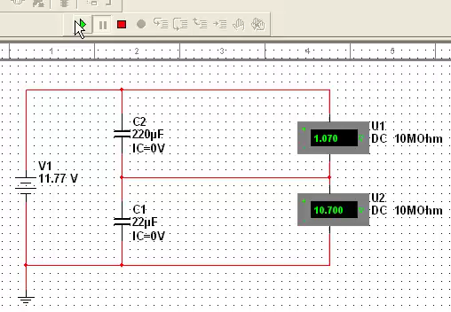
I got worried about this thing very much.I performed the same experiment on computer and other practically.I took two real capacitors 220uF@16V and 22uF@16V and one real multimeter and one breadboard with 12V power supply.

The 12V power supply gives around 11.77V when checked by multimeter.

The results of Computer Simulation on Matlab are like this:


Vcc=Vc1+Vc2

Vcc=5.888V+5.882V

Vcc=11.77V

Mathematically I got these results

Vcc=Vc1+Vc2

Vcc=1.07V+10.7V

Vcc=11.77V

Practically I got these results

Vcc=Vc1+Vc2

Vcc=1.19V+10.36V

Vcc=11.55V approximately equals to 11.77V

Error=11.77V-11.55V=0.22V

This 0.22V error is generated due to various reasons, resistances of wires,not 100% accurate rated capacitors, stray capacitances,and the list goes on and on.

The next questions was which results to accept, there are three results
a)Multi Sim
b)Mathematic
c)Pracitcal


I know Mathematic results are 100% correct, no doubt in that.So I must accept the result which is more closer to the mathematic.So practical results are more near to Multisim results.So I conclude that Multi sim results are wrong, very wrong.Practical results are more correct and even though the result includes error, the result is correct

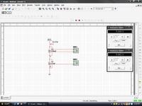
Practically I did this:


multisim junction

I think you basically didn't understand the method of DC analysis in circuit simulator, e. g. Multisim. The DC analysis result is steady state, the voltage distribution after all transient processes have finished (may be after 1 µs or a million years, depending on the circuit). With 220 uF and a typical 10 MOhm instrument input resistance, you get a time constant of 2200 sec or 36 minutes. Transient processes may be finished after, let's say 3 time constants, so you have to wait about 2 hours for the result. The second point is this: A electrolytic capacitor is far from being an ideal component, it has a considerable leak current or parallel resistance, unlike the MultiSim capacitor. Thus the real circuit may possibly have a different steady state voltage than the ideal circuit.

To see what happens in the real circuit in a limited time intervall after applying a voltage, you should use MultiSim (or any other circuit simulators) transient analysis.
 

multisim breadboard vcc

Mulitisim is good for some simulations, such as bipolar junction transistors or resistor network analysis. I have received many inacurrate simulation results for capacitor circuits when using Multisim and NI Multisim version 10.034.

The technical explanation for why Multisim yields such poor contradictory results when solving for voltages across two capacitors in series is debatable. But Multisim gives wrong results for capacitor circuits whether using AC or DC sources. Therefore it is best to build and test circuits using a bread board, components and power supplys to get real world practical results that will be identical or nearly identical to your calculations. And yes, your calculations are correct.
 

multisim in pakistan

Thanks for the reply. It was hard to believe in it, but yes, it had given me incorrect voltages. I mailed about this to Multisim too on the date I created that post, but I didn't recieve any mail from them.
What wrong have you experience in MultiSim?
 

Re: multisim giving me wrong results

I was just playing with the multisim and I thought of making a series circuit consisting of two capacitors just for nothing.
C1=0.1uF
C2=0.2uF

Vcc=12V

so Vc1=C2/(C1+C2)*Vcc=8V
Vc2=C1/(C1+C2)*Vcc=4V

I must have 8V and 4V across capacitors, but MultiSim was showing 6.003V and 5.997V.

What could be wrong? I have tried both the polar and the non-polar capacitors.


What did you say? What is wrong?

- - - Updated - - -

Mathematically I got these results

Vcc=Vc1+Vc2

Vcc=1.07V+10.7V

Vcc=11.77V

8585975500_1353201038.png
 

Attachments

  • capacitors in series.zip
    411.5 KB · Views: 106
Last edited:

I don't see the point of reopening this thread after 4+ years
 

I don't see the point of reopening this thread after 4+ years
In particular it continuous the deficiency of the original posts not to reveal the analysis type or tell about the time point when the shown measurement has been taken. The simulation film clears things up a bit, but the pretty expectable result could be better explained in a few words or shown in voltage-time diagram, I think.
 

I don't see the point of reopening this thread after 4+ years
I reached this page during google search. It was with thousands of hits. I strongly believd it was leading visitors to wrong conclusions although FvM was trying to explain but was rather suppressed.
 
Last edited:
  • Like
Reactions: FvM

    FvM

    Points: 2
    Helpful Answer Positive Rating
I strongly believd it was leading visitors to wrong conclusions although FvM was trying to explain but was rather suppressed.
I agree that umery2k75's last post raises the impression, that an actual Multisim bug had been revealed. I'm sure, Multisim has some bugs, but there's no indication of it in the present case. In so far, the thread has left a need for correction. I guess, I missed the last post, otherwise I would have posted a timely comment.

In general, I think it's just impossible to correct all erroneous believes expressed in edaboard posts (apart from the possibility that you and I are mistaken from time to time, too).
 
Didn`t we have a similar discussion (DC voltage distribution in case of two IDEAL capacitors in series) some time ago?
See here:
https://www.edaboard.com/threads/268956/
I am sure - it is NOT a MULTISIM bug. Each simulator will show a similar effect if
* there are no leakage parallel resistances , or
* ideal probes with infinite input resistances are used.

It is simply an undefined state because of idealized conditions (How does the charging process looks like vs. time for ideal capacitors ?)

- - - Updated - - -

Because of this undefined conditions the simulator requires that each node has a dc path to ground or to a voltage source.
 
Last edited:
As far as I remember.... I did exactly as Fvm instructed me to do keeping in mind the transient effect and time constants of the circuit. I remember about altering multisim DC analysis parameters. The end results were the same as observed before to me. Maybe numerical analysis is yet better to be studied to get a bigger picture of these simulators. I remember I studied "Electronic Circuit & System Simulation Methods" by Lawrence Pillage afterward for this problem. This book can give you insight as how they solves the circuit equations.
 

Hello umery2k75,

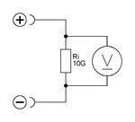
it's a simple answer for your question. All who have answered don't think about the internal resistors of the instruments, becaus the simulation works with an endless internal resistor (normaly 10 GΩ).
Innenwiderstand Voltmeter.JPG

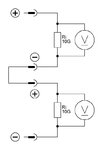
In DC simulation you only put two resistors in series and you are measuring the voltage across this resistors. If the two resistors are equal you have 1/2 voltage on each.
Innenwiderstand Voltmeter 1.JPG

In DC mode their is no current through the two capacitators, only the charging current, when power supply is switch on. After disconnecting thepower the internal resistor of the voltage meters discharge the capacitators. So you see the a slower dropping of the reading.

Regards

Rainer
 

All who have answered don't think about the internal resistors of the instruments
You may want to review the discussion. Everything has been said 4 years ago.
 

Starting date is a different point. I was referring to instrument resistance. It has been already discussed in detail, most contributors did understand that it's causing the observed effects.
 

Status
Not open for further replies.

Similar threads

Part and Inventory Search

Welcome to EDABoard.com

Sponsor

Back
Top